Board Installation Guidelines: IPU Platform F2000X-PL
Last updated: December 10, 2024
1.0 About this Document
The purpose of this document is to help users prepare their server and install the IPU Platform F2000X-PL. After reviewing this document, a user shall be able to:
- Set up their server environment according to the Best Known Configuration (BKC)
- Install an F2000X device into a supported server platform
- Attach all required peripherals
1.1 Audience
The information in this document is intended for customers evaluating the IPU Platform F2000X-PL. The card is an acceleration development platform (ADP) intended to be used as a starting point for evaluation and development. This document will cover key topics related to server bring-up and physical platform installation, with links for deeper dives on the topics discussed therein.
Note: Code command blocks are used throughout the document. Comments are preceded with '#'. Full command output may not be shown.
Table 1: Terminology
| Term | Description |
|---|---|
| AER | Advanced Error Reporting, The PCIe AER driver is the extended PCI Express error reporting capability providing more robust error reporting. |
| AFU | Accelerator Functional Unit, Hardware Accelerator implemented in FPGA logic which offloads a computational operation for an application from the CPU to improve performance. Note: An AFU region is the part of the design where an AFU may reside. This AFU may or may not be a partial reconfiguration region |
| BBB | Basic Building Block, Features within an AFU or part of an FPGA interface that can be reused across designs. These building blocks do not have stringent interface requirements like the FIM's AFU and host interface requires. All BBBs must have a (globally unique identifier) GUID. |
| BKC | Best Known Configuration, The exact hardware configuration Intel has optimized and validated the solution against. |
| BMC | Board Management Controller, Acts as the Root of Trust (RoT) on the Intel FPGA PAC platform. Supports features such as power sequence management and board monitoring through on-board sensors. |
| CSR | Command/status registers (CSR) and software interface, OFS uses a defined set of CSR's to expose the functionality of the FPGA to the host software. |
| DFL | Device Feature List, A concept inherited from OFS. The DFL drivers provide support for FPGA devices that are designed to support the Device Feature List. The DFL, which is implemented in RTL, consists of a self-describing data structure in PCI BAR space that allows the DFL driver to automatically load the drivers required for a given FPGA configuration. |
| FIM | FPGA Interface Manager, Provides platform management, functionality, clocks, resets and standard interfaces to host and AFUs. The FIM resides in the static region of the FPGA and contains the FPGA Management Engine (FME) and I/O ring. |
| FME | FPGA Management Engine, Provides a way to manage the platform and enable acceleration functions on the platform. |
| HEM | Host Exerciser Module, Host exercisers are used to exercise and characterize the various host-FPGA interactions, including Memory Mapped Input/Output (MMIO), data transfer from host to FPGA, PR, host to FPGA memory, etc. |
| Intel VT-d | Intel Virtualization Technology for Directed I/O, Extension of the VT-x and VT-I processor virtualization technologies which adds new support for I/O device virtualization. |
| IOCTL | Input/Output Control, System calls used to manipulate underlying device parameters of special files. |
| JTAG | Joint Test Action Group, Refers to the IEEE 1149.1 JTAG standard; Another FPGA configuration methodology. |
| MMIO | Memory Mapped Input/Output, Users may map and access both control registers and system memory buffers with accelerators. |
| OFS | Open FPGA Stack, A modular collection of hardware platform components, open source software, and broad ecosystem support that provides a standard and scalable model for AFU and software developers to optimize and reuse their designs. |
| OPAE SDK | Open Programmable Acceleration Engine Software Development Kit, A collection of libraries and tools to facilitate the development of software applications and accelerators using OPAE. |
| PAC | Programmable Acceleration Card: FPGA based Accelerator card |
| PIM | Platform Interface Manager, An interface manager that comprises two components: a configurable platform specific interface for board developers and a collection of shims that AFU developers can use to handle clock crossing, response sorting, buffering and different protocols. |
| PR | Partial Reconfiguration, The ability to dynamically reconfigure a portion of an FPGA while the remaining FPGA design continues to function. In the context of Intel FPGA PAC, a PR bitstream refers to an Intel FPGA PAC AFU. Refer to Partial Reconfiguration support page. |
| RSU | Remote System Update, A Remote System Update operation sends an instruction to the Intel FPGA PAC D5005 device that triggers a power cycle of the card only, forcing reconfiguration. |
| SR-IOV | Single-Root Input-Output Virtualization, Allows the isolation of PCI Express resources for manageability and performance. |
| TB | Testbench, Testbench or Verification Environment is used to check the functional correctness of the Design Under Test (DUT) by generating and driving a predefined input sequence to a design, capturing the design output and comparing with-respect-to expected output. |
| UVM | Universal Verification Methodology, A modular, reusable, and scalable testbench structure via an API framework. |
| VFIO | Virtual Function Input/Output, An IOMMU/device agnostic framework for exposing direct device access to user space. |
Table 2: Related Documentation
| Name |
|---|
| [Automated Evaluation User Guide: OFS for Agilex® 7 SoC Attach FPGAs] |
| [Shell Technical Reference Manual: OFS for Agilex® 7 SoC Attach FPGAs] |
| [Software Reference Manual: Open FPGA Stack] |
| [Shell Developer Guide: OFS for Agilex® 7 SoC Attach FPGAs] |
| [Workload Developer Guide: OFS for Agilex® 7 SoC Attach FPGAs] |
| [Security User Guide: Open FPGA Stack] |
| [KVM User Guide: Open FPGA Stack] |
| [Docker User Guide: Open FPGA Stack] |
| [OFS 2024.1 F2000X-PL Release Notes] - under "Important Notes" |
| Cyclone® 10 LP Board Management Controller (BMC) User Guide for Intel® IPU F2000X-PL v1.2.4 (Document ID: 789706) 1 |
1 Work with your Altera sales representative for access.
1.2 Server Requirements
The following requirements must be met when purchasing a server to support the IPU Platform F2000X-PL.
1.2.1 Host Server Specifications
The host server must meet the following minimal specifications:
- The server platform must contain at least 64GiB of RAM to to compile the Yocto or FIM images
- If using the server platform to build a Yocto image, it is recommended to have at least 200 GB of free storage space
1.2.2 Host BIOS
Te Host BIOS settings known to work with the IPU Platform F2000X-PL:
- PCIe slot width must be x16
- PCIe slot speed must be 4
- PCIe slot must have iommu enabled
- Intel VT for Directed I/O (VT-d) must be enabled
Specific BIOS paths are not listed here, as they can differ between BIOS vendors and versions.
1.2.3 Host Server Kernel and GRUB Configuration
While many host Linux kernel and OS distributions may work with this design, only the following configuration(s) have been tested:
- Ubuntu 22.04 LTS, 6.1.78-dfl
1.3 Server Forced Air Cooling
The IPU Platform F2000X-PL is a high-performance processing card with a passive heat sink to dissipate device heat and must be installed in a server with sufficient forced airflow cooling to keep all devices operating below maximum temperature. The table below lists the thermal terms and descriptions used in thermal analysis.
Table 5: Thermal Terms and Descriptions
| Term | Description |
|---|---|
| Cubic Feet per Minute (CFM) | Volumetric airflow rate, in cubic feet per minute, of air passing through faceplate. |
| Tj | FPGA Junction Temperature |
| TLA | Local Ambient temperature. Temperature of forced air as it enters the IPU Platform F2000X-PL. Note: In many systems, this is higher than the room ambient due to heating effects of chassis components. |
Note: The FPGA junction temperature must not exceed 100°C. The case temperature of the QSFP modules must meet the module vendor's specification.
Note: The table below provides the thermal targets for which the IPU Platform F2000X-PL was designed. As a card manufacturer, you must qualify your own production cards.
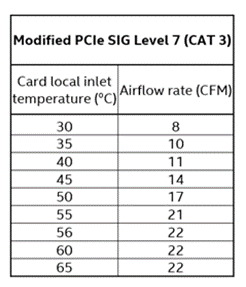
The maximum card inlet air temperatures must support continuous operation under the worst-case power scenario of 150W TDP.
The airflow requirements for optimal heat sink performance at minimum is characteristic of CAT 3 servers or PCIe SIG Level 7 thermal profiles, in both, forward & reverse flow, see figure below:
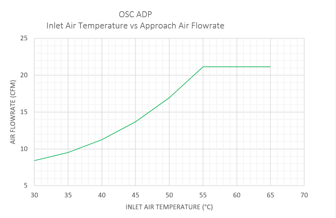
As the IPU Platform F2000X-PL is a development platform, it is not integrated into the server baseband management controller closed loop cooling control. It is strongly recommended that you set your server's fan settings to run constantly at 100% with the server chassis lid closed to prevent unwanted IPU Platform F2000X-PL thermal shutdown.
1.4 External Connections
Figure 1: External Connections
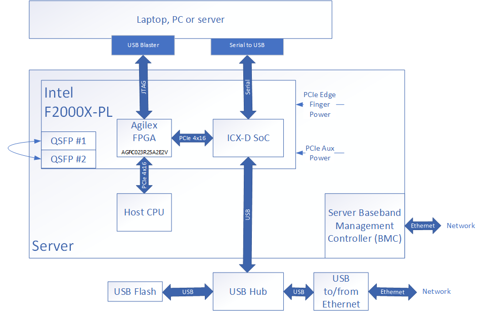
The items listed Table 6 in are known to work for external connectivity. Specific links are given for convenience, other products may be used but have not been tested.
Table 6: External Connection Cables
| Item | Part Number | Link to source |
|---|---|---|
| RS-232 to USB Adapter | DTECH FTDI USB to TTL Serial Adapter, 3 m | USB to TTL Serial |
| USB to Ethernet Adapter, Aluminum 3 Port USB 3.0 | Teknet | USB Hub with Ethernet adapter |
| Flash Drive, 64 GB or larger | SanDisk | |
| QSFP DAC Cable | FS.com Generic 2m 100G QSP28 Passive Direct Attach Copper | QSFP28 DAC |
| (optional) Intel FPGA Download Cable II | PL-USB2-BLASTER | USB-Blaster II |
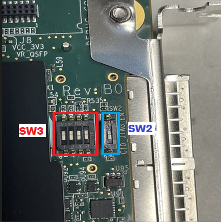
1.5 Preparing the IPU Platform F2000X-PL for Installation
Turn the board over to back side and remove the Kapton tape covering switches SW2 and SW3 and make sure the switches are set as shown in Figure 1.
Table 7: Switch Settings
| Name | Value |
|---|---|
| SW3.1 | off |
| SW3.2 | off |
| SW3.2 | on |
| SW3.2 | off |
| SW2 | off |
Figure 2: Board Switch Settings
1.5.1 USB to Serial Adapter
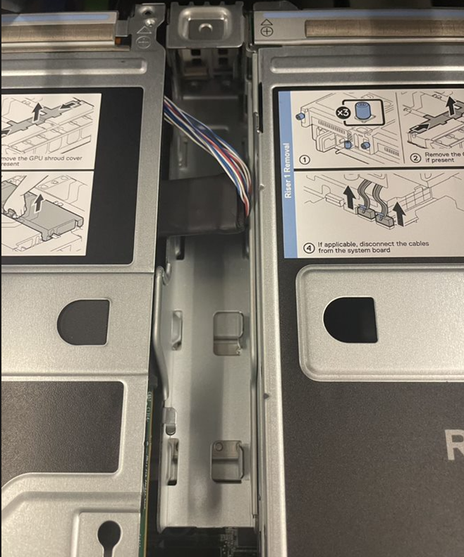
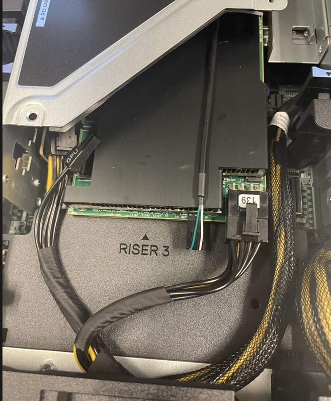
The IPU Platform F2000X-PL has a serial UART for access located on back edge of the board. This connection is useful for making BIOS and boot settings and for monitoring the SoC. In most servers, you will need to remove a riser card and route the USB to serial cable and (optional) Intel FPGA USB Blaster through an unused PCIe slot above or below where the IPU is installed. See Figure 3 for an example of cable routing.
Figure 3: Cable Routing

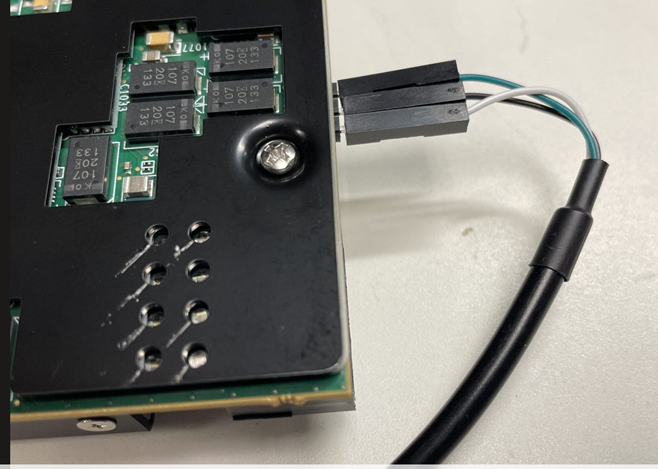
The USB to serial connection is shown in Figure 4 where the White wire is TXD, Black wire is ground and Green wire is RXD.
Figure 4: USB to Serial Adapter connection
1.5.2 IPU JTAG
The IPU Platform F2000X-PL provides a 10 pin JTAG header for FPGA and Cyclone 10 Board Management Controller development work using a Intel FPGA Download Cable II. This JTAG connection is optional for initial bring-up but is useful for manual image reprogramming and debug. See Figure 5 noting the orientation of the connection. The orientation of the USB Blaster II requires careful installation in a PCIe bay that has additional room in the adjacent bay. This may require you to either install the board over the PSU of the server, or to temporarily remove an adjacent riser while programming.
Figure 5: USB Blaster II Connection
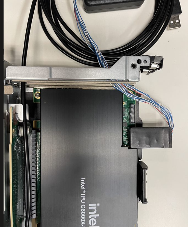
Figure 6: USB Blaster II Installation
1.5.3 Power
The IPU Platform F2000X-PL must receive power from both the 12 V and 3.3V PCIe slot and the 12 V Auxiliary 2×4 power connector. The board does not power up if any of the 12 V and 3.3 V PCIe slot, or 12 V Auxiliary power sources are disconnected.
PCIe specifications define 12 V Auxiliary power connector pin assignment. The IPU Platform F2000X-PL implements an 8-position right angle (R/A) through-hole PCB header assembly on the top right side of the board as depicted in the picture below.
Figure 7: 12V PCIe AUX Connector Location
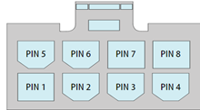
Refer the table below for pinout details.
Table 8: 12V (2x3) AUX Connector Pin Out
| Pin | Description |
|---|---|
| 1 | +12V |
| 2 | +12V |
| 3 | +12V |
| 4 | Sense 1 |
| 5 | Ground |
| 6 | Sense 0 |
| 7 | Ground |
| 8 | Ground |
See Auxiliary power connection in Figure 8.
Figure 8: Auxiliary Power Connection
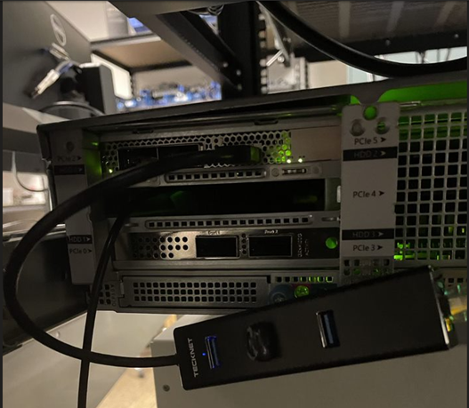
1.5.4 USB Hub Connection
The USB Hub is connected to the USB type A connector on the front panel. Additionally, attach a network connected Ethernet connection to the USB hub. See Figure 9.
Figure 9: USB Hub Connection
1.5.5 Creating a Bootable USB Flash Drive for the SoC
Connect your flash drive to an available Linux host. In this section the USB will set up to be used as a secondary boot source for the SoC and will also be used to update the NVMe from which the ICX-D SoC boots in section 2.1 Updating the F2000X-PL ICX-D SoC NVMe.
You will load the latest pre-compiled Yocto core-image-minimal WIC image into USB flash. This image can be downloaded from
ofs-2024.1-1 Release for Agilex 7 SoC Attach Reference Shell, under assets, or compiled from meta-ofs. Compilation is discussed in section 4.0 Compiling a Custom Yocto SoC Image.
-
Insert a 64 GB or larger USB Flash Drive into the USB slot of a computer/server you can use to format the drive. The following instructions assume you are using some flavor of GNU+Linux. You need sudo access privileges on this machine.
-
In a terminal window, find the device name of the USB flash drive and unmount the device:
$ lsblk

NAME MAJ:MIN RM SIZE RO TYPE MOUNTPOINT
sda 8:0 0 1.8T 0 disk
├─sda1 8:1 0 600M 0 part /boot/efi
├─sda2 8:2 0 1G 0 part /boot
└─sda3 8:3 0 1.8T 0 part
├─rhel-root 253:0 0 50G 0 lvm /
├─rhel-swap 253:1 0 4G 0 lvm \[SWAP\]
└─rhel-home 253:6 0 1.7T 0 lvm /home
sdb 8:16 0 447.1G 0 disk
├─sdb1 8:17 0 600M 0 part
├─sdb2 8:18 0 1G 0 part
└─sdb3 8:19 0 445.5G 0 part
├─fedora_localhost\--live-swap 253:2 0 4G 0 lvm
├─fedora_localhost\--live-home 253:3 0 301G 0 lvm
├─fedora_localhost\--live-root 253:4 0 70G 0 lvm
└─fedora_localhost\--live-centos_root 253:5 0 70.5G 0 lvm
sdd 8:48 1 57.3G 0 disk
└─sdd1 8:49 1 57.3G 0 part
In the above example, the 64 GB USB Flash device is designated
sdd. Note, your device file name may be different. You are looking for an entry that matches the size of your USB Flash. You can also check the output ofdmesgafter manually plugging in your USB Flash device to view the name the kernel has given it in an auto-generated event. -
Unmount the USB flash (if not already unmounted).
-
Download the Yocto WIC image. To prevent boot errors that may arise when using the same boot image loaded in both USB flash and on-board NVMe, you must choose an older version of the Yocto WIC to load onto the USB. Browse the tagged Yocto release images on GitHub and choose the second newest release image as the temporary USB boot target. In this example we will use the OFS 2023.1 RC3 release. You will also need to download the newest Yocto release image (core-image-full-cmdline-intel-corei7-64-20240227185330.rootfs.wic.gz).
# Download an older version of the Yocto release image to use as the USB boot target, version 2023.1 RC3 shown here $ wget https://github.com/OFS/meta-ofs/releases/download/ofs-2023.1-3/core-image-full-cmdline-intel-corei7-64-20230505161810.rootfs.wic.gz $ wget https://github.com/OFS/meta-ofs/releases/download/ofs-2023.1-3/core-image-full-cmdline-intel-corei7-64-20230505161810.rootfs.wic.gz.sha256 # Verify the checksum of the downloaded image $ sha256sum -c https://github.com/OFS/meta-ofs/releases/download/ofs-2023.1-3/core-image-full-cmdline-intel-corei7-64-20230505161810.rootfs.wic.gz.sha256 # Uncompress the package $ gzip -d core-image-full-cmdline-intel-corei7-64-20230505161810.rootfs.wic.gz # Download the most recent Yocto release image, which will overwrite on-board NVMe $ wget https://github.com/OFS/meta-ofs/releases/download/ofs-2024.1-2/core-image-full-cmdline-intel-corei7-64-20240227185330.rootfs.wic $ wget https://github.com/OFS/meta-ofs/releases/download/ofs-2024.1-2/core-image-full-cmdline-intel-corei7-64-20240227185330.rootfs.wic.sha256 # Verify the checksum of the downloaded image sha256sum -c core-image-full-cmdline-intel-corei7-64-20240227185330.rootfs.wic.sha256 # Uncompress the package $ gzip -d core-image-full-cmdline-intel-corei7-64-20240227185330.rootfs.wic -
Copy core-image-full-cmdline-intel-corei7-64-20230505161810.rootfs.wic to the USB flash. This process may take several minutes.
-
Create a partition to store the Yocto image, which will be used to overwrite on-board NVMe as the default boot target.
$ sudo fdisk /dev/sdd Command (m for help): p Command (m for help): n Partition number (4-128, default 4): <<press enter>> First sector (14617908-125045390, default 14618624): <<press enter>> Last sector, +/-sectors or +/-size{K,M,G,T,P} (14618624-125045390, default 125045390): <<press enter>> Created a new partition 4 of type 'Linux filesystem' and of size 92 GiB. Command (m for help): p Command (m for help): w -
Verify USB flash is partitioned.
-
Format the new partition.
-
Copy compressed
core-image-minimalWIC into /mnt.
Remove the USB flash from the Linux computer and install the flash drive in the USB hub attached to the IPU Platform F2000X-PL.