oneAPI Accelerator Support Package(ASP) Reference Manual: Open FPGA Stack
1.0 Overview
1.1 About this Document
This document serves as a reference manual for platform designers wanting to enable oneAPI support on their Open FPGA Stack(OFS) platforms. The document describes essential hardware and software components required for enabling this design flow using OFS. Implementation details for oneapi-asp for Open FPGA Stack(OFS) reference platforms is covered towards the end of the document.
Note: Table 1-1 in oneAPI Accelerator Support Package (ASP): Getting Started User Guide lists OFS reference platforms.
For more information about developing application kernels for FPGA using oneAPI Base Toolkit (Base Kit) refer to Intel® FPGA Add-on for oneAPI Base Toolkit webpage.
1.2 Terminology
This table defines some of the common terms used when discussing OFS.
Table 1-1: Terminology
| Term | Abbreviation | Description |
|---|---|---|
| Open FPGA Stack | OFS | A modular collection of hardware platform components, open source software, and broad ecosystem support that provides a standard and scalable model for AFU and software developers to optimize and reuse their designs. |
| Accelerator Functional Unit | AFU | Hardware Accelerator implemented in FPGA logic which offloads a computational operation for an application from the CPU to improve performance. Note: An AFU region is the part of the design where an AFU may reside. This AFU may or may not be a partial reconfiguration region. |
| FPGA Interface Manager | FIM | Provides platform management, functionality, clocks, resets and standard interfaces to host and AFUs. The FIM resides in the static region of the FPGA and contains the FPGA Management Engine (FME) and I/O ring. |
| High Level Design | HLD | For the purpose of this guide, this term refers to designing with High Level Design tools like oneAPI Base Toolkit (Base Kit). |
| oneAPI Accelerator Support Package | oneAPI ASP | A collection of hardware and software components that enable oneAPI kernel to communicate with oneAPI runtime and other OFS hardware, software components. oneAPI ASP hardware components and oneAPI kernel form the AFU region of a oneAPI system in OFS. |
| Intel® FPGA Basic Building Blocks | BBB | Basic Building Blocks (BBB) for Altera® FPGAs is a suite of application building blocks and shims like Memory Properties Factory (MPF). |
| BBB Memory Properties Factory | BBB MPF | Intel® FPGA BBB MPF block provides features like virtual to physical address (VTP), ordering read responses, read/write hazard detection, and masked (partial) writes. oneapi-asp uses MPF VTP feature. |
| Open Programmable Acceleration Engine Software Development Kit | OPAE SDK | A collection of libraries and tools to facilitate the development of software applications and accelerators using OPAE. |
| Platform Interface Manager | PIM | An interface manager that comprises two components: a configurable platform specific interface for board developers and a collection of shims that AFU developers can use to handle clock crossing, response sorting, buffering and different protocols. |
| Device Feature List | DFL | A concept inherited from OFS. The DFL drivers provide support for FPGA devices that are designed to support the Device Feature List. The DFL, which is implemented in RTL, consists of a self-describing data structure in PCI BAR space that allows the DFL driver to automatically load the drivers required for a given FPGA configuration. |
| Best Known Configuration | BKC | The exact hardware configuration that the solution has been optimized and validated against. |
| SYCL | - | SYCL (pronounced "sickle") is a royalty-free, cross-platform abstraction layer that enables code for heterogeneous and offload processors to be written using modern ISO C++ (at least C++ 17). It provides several features that make it well-suited for programming heterogeneous systems, allowing the same code to be used for CPUs, GPUs, FPGAs or any other hardware accelerator. SYCL was developed by the Khronos Group, a non-profit organization that develops open standards (including OpenCL™) for graphics, compute, vision, and multimedia. SYCL is being used by a growing number of developers in a variety of industries, including automotive, aerospace, and consumer electronics. |
| Data Parallel C++ | DPC++ | DPC++ is Intel’s implementation of the SYCL standard. It supports additional attributes and language extensions which ensure DCP++ (SYCL) is efficiently implanted on Intel hardware. |
| Installable Client Driver | ICD | Intel® FPGA Runtime for OpenCL™ Software Technology supports the OpenCL ICD extension from the Khronos Group™. The OpenCL ICD extension allows you to have multiple OpenCL implementations on your system. With the OpenCL ICD Loader Library, you may choose from a list of installed platforms and execute OpenCL API calls that are specific to your OpenCL implementation of choice. |
| FPGA Client Driver | FCD | Intel® FPGA Runtime for OpenCL™ Software Technology supports FPGA Client Driver(FCD) extension. FCD allows the runtime to automatically find and load the oneAPI ASP libraries at host run time |
Note:
oneapi-aspwas referred to asofs-hld-shimin OFS (for Agilex® 7 FPGA & Stratix® 10 FPGA) and OpenCL AFU Shim (ofs-opencl-afu-shim) in OFS early access(EA) release (for Stratix® 10 FPGA with Intel® FPGA PAC D5005 as reference platform).
1.3 Prerequisites
The content in this manual requires readers to be familiar with:
- Hardware and software components of Open FPGA Stack, especially the following:
- FPGA Interface Manager(FIM)
- Stratix® 10 FPGA:
- Agilex® 7 FPGA:
- Accelerator Functional Unit(AFU)
- Stratix® 10 FPGA: Workload Developer Guide: OFS for Stratix® 10 PCIe Attach FPGAs
- Agilex® 7 FPGA: Workload Developer Guide: OFS for Agilex® 7 PCIe Attach FPGAs
- Software Reference Manual: Open FPGA Stack (OPAE SDK and Linux-DFL section)
- ofs-platform-afu-bbb
- FPGA Interface Manager(FIM)
In addition to above, developers must be familiar with the following tools & concepts:
- Quartus® Prime Design Software (Quartus® software revisions, Platform Designer, compilation Flows, timing analysis, compilation reports, understanding FPGA resource utilization, programming Altera® FPGAs)
- Partial Reconfiguration (PR)
- FPGA Peripheral IPs (PCIe, External Memory IP, Ethernet IP)
- Avalon® Interface
- Scripting (TCL, Python, Shell scripts)
- Verilog, SystemVerilog
- C++
- Familiarity with SYCL
- Familiarity with oneAPI compilation process for FPGAs & oneAPI code samples
- Familiarity with oneAPI Accelerator Support Package (ASP): Getting Started User Guide
1.4 Introduction to oneAPI on Open FPGA Stack(OFS)
The Intel® oneAPI Base Toolkit (Base Kit) is a core set of tools and libraries for developing high-performance, data-centric applications across diverse architectures (CPUs, GPUs and FPGAs). It features an industry-leading C++ compiler that implements SYCL, an evolution of C++ for heterogeneous computing.
Figure 1-1 shows the high-level representation of oneAPI application developers using FPGAs for acceleration. The runtime flow consists of a host code running on a processor and an application kernel code running on an FPGA. Open FPGA Stack enables vendors to enable support for this flow on their platforms.
Figure 1-1: oneAPI Application on OFS Platforms

oneAPI Base Toolkit (Base Kit) consists of a compiler and runtime environment. The compiler converts a SYCL kernel (FPGA application code) into a hardware circuit. This hardware circuit requires additional logic to communicate with the runtime and FPGA board peripherals. This additional logic is provided by oneAPI Accelerator Support Package(oneAPI ASP). oneAPI ASP consists of hardware components that enable this generated hardware circuit to communicate with the host processor as well as software components that enable the runtime to identify and communicate with the kernel.
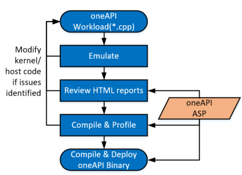
Figure 1-2 shows the workload design steps and steps in which the oneAPI Base Toolkit (Base Kit) requires oneAPI ASP as input. For more information about workload development and how workload developers target a specific platform during compilation, refer to Intel oneAPI Programming Guide and Intel® oneAPI DPC++/C++ Compiler Handbook for Intel® FPGAs. The next section introduces oneAPI ASP.
Figure 1-2: High Level Design Flow for FPGAs with oneAPI Base Toolkit (Base Kit)
1.5 Introduction to oneAPI Accelerator Support Package(ASP)
As mentioned in previous section, oneAPI ASP is a collection of hardware and software components that interface with the hardware circuit generated by the oneAPI compiler. The hardware circuit generated by the oneAPI compiler from a oneAPI kernel is referred to as the kernel system. While the kernel system consists of logic controlled by the workload developer's specifications, the kernel system interfaces are generated by the oneAPI compiler based on specifications provided by the oneAPI ASP designer. These specifications are input to the compiler using XML files (discussed in section 2.0).
Note: All the interfaces generated by the oneAPI compiler are Avalon® Interfaces.
Figure 1-3: Kernel System Interfaces
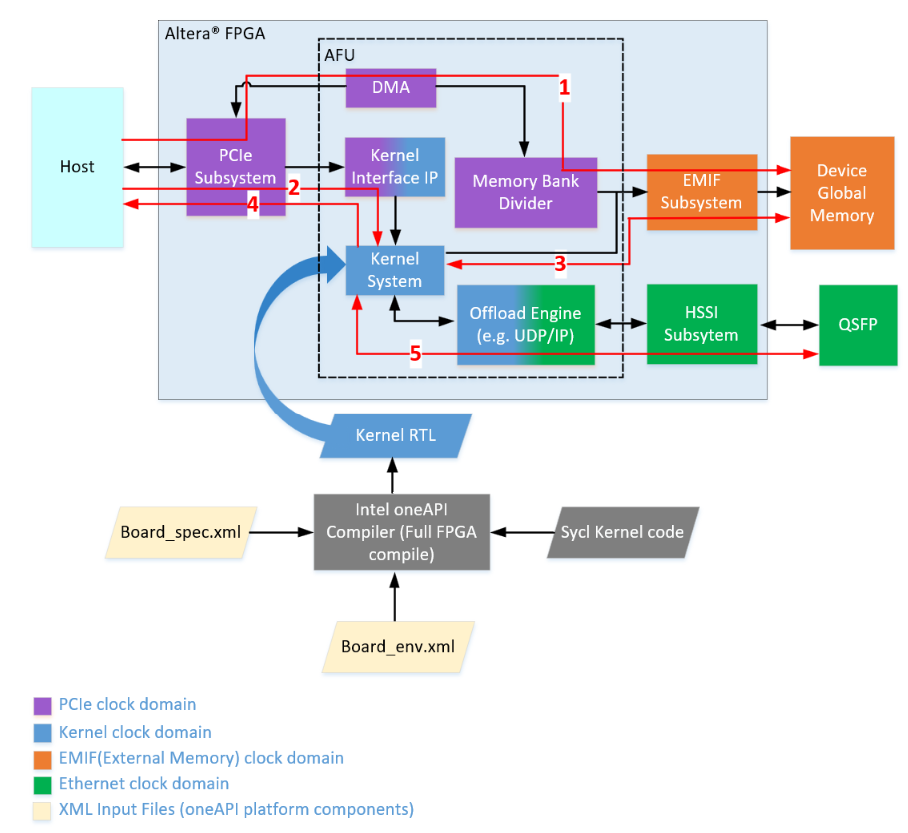
Figure 1-3 shows a high-level representation of an OFS hardware design and interfaces to/from kernel_system. The numbered arrows depict the following:
- Path 1 represents host-to-External Memory Interface (EMIF)
- Path 2 represents the host to kernel interface
- Path 3 represents kernel to EMIF
- Path 4 represents kernel to Unified Shared Memory (USM) Interface
- Path 5 represents kernel to HSSI interface
oneAPI ASP hardware components can be divided into 3 categories:
- RTL components: constituting various interface logic, for example, host to External Memory Interface (EMIF), kernel to EMIF interface, host to kernel interface, kernel to host memory interface as well as additional components to handle kernel control signals and perform Direct Memory Access (DMA)
- XML files: for describing hardware interfaces and compilation environment to oneAPI Base Toolkit (Base Kit)
- Scripts: to control compile flow
In addition to the hardware components, a software layer is required for handling I/O operations between oneAPI runtime and the board. The oneAPI ASP software layer can be divided into 2 categories:
- Memory Mapped Device (MMD) Layer: required by the host & runtime to communicate with the oneAPI kernel & other oneAPI ASP hardware registers
- oneAPI ASP utilities: required to setup and diagnose the board
The MMD uses API provided by OPAE SDK to communicate with the device. The FPGA driver is provided by the linux-DFL kernel driver.
Figure 1-4 shows how the above oneAPI ASP components tie into Open FPGA Stack.
Figure 1-4: Open FPGA Stack (OFS) components

2.0 XML Files in oneAPI ASP
The kernel system interfaces generated by the oneAPI compiler are based on specifications provided by oneAPI ASP developer. An XML file, called board_spec.xml is used to pass the specifications to the oneAPI compiler. oneAPI ASP developers must create this XML file for their boards.
In addition to board_spec.xml, the oneAPI Base Toolkit (Base Kit) relies on another XML file called board_env.xml to get information about the board environment. The board_env.xml file helps the runtime setup board installation.
The next section explains the contents of board_spec.xml. Section 2.2 covers contents of board_env.xml file.
2.1 board_spec.xml File
A typical board_spec.xml structure is shown in Fig 2-1. In addition to kernel system interfaces, the board_spec.xml file is also used to specify other compilation details like Quartus® Prime Pro Edition Software version used in platform design, compilation scripts to help control Quartus® software compile flows, FPGA resource utilization details.
Elements of board_spec.xml file are summarized in table 2-1. Each element has additional attributes and parameters. Details are covered in respective sections for each element.
Figure 2-1: board_spec.xml File Structure
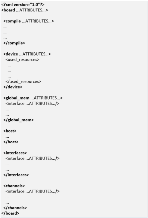
Table 2-1: Elements of board_spec.xml
| Element | Use of Element | Attributes |
|---|---|---|
| board | Used to specify a name for the board and the version of Quartus® Prime Pro Edition Software used to develop the platform design. This board name is used to identify the board design to be compiled and must match the name of the directory in which board_spec.xml resides. | version, name |
| compile | Used to describe different compile flows | project, revision, qsys_file, generic_kernel, generate_cmd, synthesize_cmd, auto_migrate |
| device | Used to specify the FPGA device model file for the FPGA part on the board. | device_model, used_resources |
| global_mem | Different attributes in this element are used to provide details about the external memory used as the global memory for the FPGA oneAPI kernel/application. | name, max_bandwidth, interleaved_bytes, config_addr, default, interface |
| host | Used to specify the offset at which the kernel resides. | kernel_config |
| interfaces | Used to specify control signals to oneAPI kernels | interface, kernel_clk_reset |
| channels | Used to describe interface to stream data directly between kernels and I/O | interface |
The compiler expects a separate board_spec.xml file for every board variant a platform supports. Board variants are different hardware design implementations for the same platform, a oneAPI ASP can have multiple board variants. A oneAPI kernel developer can select the board variant suitable for their application at compile time.
A board_spec.xml file must be located at the top most level of each board variant's hardware directory (the hardware directory is specified by board_env.xml, please refer to section 2.2 for details on hardware element). For example, a separate board_spec.xml file for each board variant for OFS reference platforms is located in oneapi-asp/Platform-Name/hardware/Board-Variant/ directory, where Platform-Name is n6001, fseries-dk, iseries-dk for OFS targeting Agilex® 7 FPGA and d5005 for OFS targeting Stratix® 10 FPGA.
2.1.1 board Element
The board element of the board_spec.xml file provides the Quartus® Prime Pro Edition Software version and the name of the board.
Table 2-2: Attributes for the board Element
| Attribute | Description |
|---|---|
| version | The version of the board. The board version should match the version of the Quartus® Prime Pro Edition Software you use to develop the platform design. The oneAPI compiler uses this value to perform environment checks for supported version during application compile |
| name | The name of the accelerator board, which must match the name of the directory in which the board_spec.xml file resides. The name must contain a combination of only letters, numbers, underscores (_), hyphens (-), or periods (.) (for example, ofs_n6000). |
Example below shows the board element populated for a board designed with Quartus® Prime Pro Edition Software version 22.3 and board variant named "Agilex_brd1".
Note: A board variant name is different from a platform directory name. Please see Note in section 2.2 for more information on board variants.
Figure 2-2: board Element

2.1.2 compile Element
Depending on the application requirements, the design may have different compilation flows and different design settings for each flow (for example, there can be a flat flow without partial reconfiguration support or a flow with partitions in the design to enable partial reconfiguration). Designers can control the flow and its settings using scripts.
To allow selection of compile flow during application compile & to describe control of Quartus® software compilation as well as registration, automigration, the compile element of the board_spec.xml file and its associated attributes and parameters are used.
Table 2-3: Attributes for compile Element
| Attribute | Description |
|---|---|
| name | Name of the compilation flow. This name can be used to differentiate between flows at oneAPI kernel compilation time. oneAPI compiler allows selecting a compile flow using -Xsbsp-flow option. |
| project | Name of the Quartus® software project file (.qpf) that the Quartus® Prime Pro Edition Software intends to compile. |
| revision | Name of the revision within the Quartus® software project that the Quartus® Prime Pro Edition Software compiles to generate the final bitstream. |
| qsys_file | Name of the Platform Designer file into which the oneAPI kernel is embedded. You have the option to assign a value of "none" to qsys_file if you do not require the Quartus® Prime Pro Edition Software to create a top-level .qsys file for your design. In this scenario, oneAPI compiler adds a .qip file into the Quartus® software project. In this case, the custom oneAPI ASP must manually instantiate the generated HDL entity (generated entity is in the kernel_system.v file). |
| generic_kernel | Set this value to 1 if you want the offline compiler to generate a common Verilog interface for all compilations. This setting is necessary in situations where you must set up design partitions around the kernel, such as in the Configuration via Protocol (CvP) flow. |
| generate_cmd | Command required to prepare for full compilation, such as to generate the Verilog files for the Platform Designer system into which the oneAPI kernel is embedded. |
| synthesize_cmd | Command required to generate the fpga.bin file from the Custom Platform. Usually, this command instructs the Quartus® Prime Pro Edition Software to perform a full compilation. |
| auto_migrate | *platform_type—Choose this value based on the value referenced in the Reference Platform from which you derive your Custom Platform. Valid values are a10_ref, s10_ref, and none. *include fixes—Comma-separated list of named fixes that you want to apply to the Custom Platform. *exclude fixes—Comma-separated list of named fixes that you do not want to apply to the Custom Platform. |
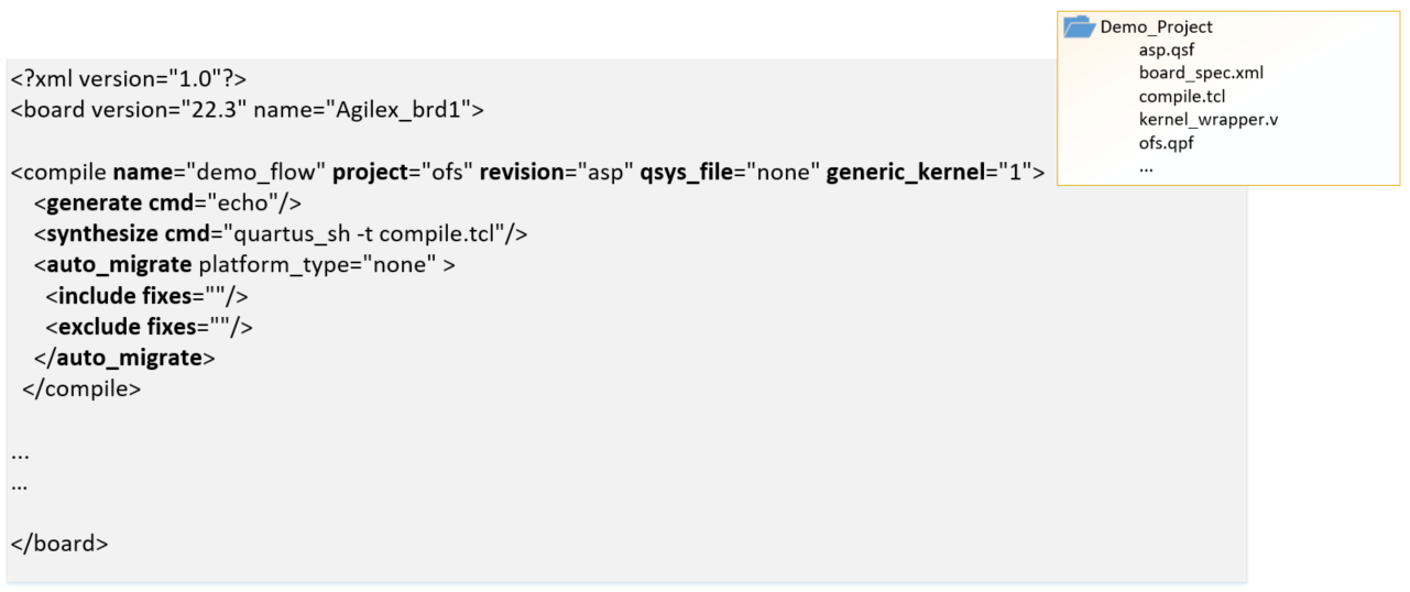
Example below shows a populated compile element for a sample Quartus® software Project called ofs.qpf, the Quartus® software revision to be compiled is called asp (asp.qsf). In this example, the compiler generates the kernel system (entity is called kernel_system) and this entity is instantiated manually in the Quartus® software project (e.g. in a file called kernel_wrapper.v), hence qsys_file is set to "none". The synthesize_cmd points to a script "compile.tcl" located in the same directory as the board_spec.xml, compile script performs all necessary system generation and compile steps for generation of final bitstream. The project directory snippet below is for demonstration only. The compile flow is named "demo_flow".
There can be multiple compile elements for the different compilation flows that a platform designer wishes to enable in their platform (e.g. different revisions with different Quartus® software settings or a PR revision).
Figure 2-3: compile Element
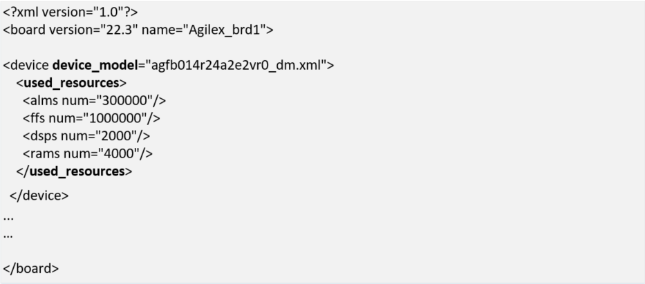
2.1.3 device Element
A device model(DM) file is an XML file that has the total resources on the device (i.e. ALMs, FFs, DSPs, RAMs). This is required for any FPGA part used in a oneAPI design. Most device model files are provided as part of the oneAPI Base Toolkit (Base Kit) installation ($INTELFPGAOCLSDKROOT/share/models/dm, where INTELFPGAOCLSDKROOT is set by the setvars.sh environment setup script provided by oneAPI toolkit). If the device model file for your part number is not included in $INTELFPGAOCLSDKROOT/share/models/dm, it must be created and placed in the same folder as board_spec.xml. A new device model file can be created using existing files as reference.
The device model file name must be specified in the device_model attribute of device element. The used_resources attribute is used to specify the resources being utilized by the oneAPI ASP and peripheral IPs. The utilization by non-kernel logic is calculated during platform design. The compiler utilizes the total resources from device model file and utilized resources in used_resources section to estimate the available resources for application kernel.
Table 2-4: Attributes for device Element
| Attribute | Description |
|---|---|
| device_model | The file name of the device model file that describes the available FPGA resources on the accelerator board. |
| used_resources | Reports the number of adaptive logic modules (ALMs), flip-flops, digital signal processor (DSP) blocks and RAM blocks that the board design consumes in the absence of any kernel. If you create a defined partition around all the board logic, you can obtain the used resources data from the Partition Statistics section of the Fitter report. Extract the information from the following parameters: * alms num — The number of logic ALMs used, excluding the number of ALMs with only their registers used. The value should correspond to [a]+[b]+[d] from part [A] of the Fitter Partition Statistics. * ffs num — The number of flip flops. * dsps num — The number of DSP blocks. * rams num — The number of RAM blocks. |
Example below shows the device element added for a Agilex® 7 FPGA based platform with device model file named "agfb014r24a2e2vr0_dm.xml". The number of used_resources are for demonstration purposes and are not to be used by oneAPI ASP developers.
Figure 2-4: device Element
2.1.4 interface Attribute
Note: This is different from the
interfaceselement discussed in upcoming sections. In the board_spec.xml file, each global memory, channel or kernel connection is comprised of individual interfaces. For theglobal_mem,channels, andinterfacesXML elements, aninterfaceattribute must be included to specify the corresponding parameters for each connection.
Table 2-5: Parameters for interface attribute
| Parameter | Description | Applicable Interface |
|---|---|---|
| name | * For global_mem: instance name of the Platform Designer component. * For channels: instance name of the Platform Designer component that has the channel interface. * For interfaces: name of the entity in which the kernel interface resides (for example, board). |
All |
| port | port parameter can be defined either inline in interface attribute or as a separate element in interface attribute. See section 2.1.4.1 for more information. |
All |
| type | * For global_mem: set to agent. * For channels: - Set to streamsource for a stream source that provides data to the kernel. - Set to streamsink for a stream sink interface that consumes data from the kernel. * For interfaces: set to either host, irq, or streamsource. |
All |
| width | * For global_mem: width of the memory interface in bits. * For channels: number of bits in the channel interface. * For interfaces: width of the kernel interface in bits. |
All |
| waitrequest_allowance | * For global_mem: [Optional] Amount of Avalon®-MM waitrequest allowance supported on the agent interface (that is, kernel-facing interface) of the clock-crossing bridge that spans between the memory and the kernel clock domains. * For kernel_cra: [Optional] Amount of Avalon®-MM waitrequest allowance that the kernel_cra agent interface must support. This parameter defaults to 0 if you do not specify it in the board_spec.xml file. A value of 0 indicates that this waitrequest allowance feature is disabled. |
All |
| maxburst | Maximum burst size for the agent interface. Attention: The value of width ÷ 8 x maxburst must be less than the value of interleaved_bytes. |
global_mem |
| address | Starting address of the memory interface that corresponds to the host interface-side address. For example, address 0 should correspond to the bank1 memory host from the Memory Bank Divider. In addition, any non-zero starting address must abut the end address of the previous memory. |
global_mem |
| size | Size of the memory interface in bytes. * For global_mem: The sizes of all memory interfaces should be equal. * For interfaces: interface can have variable sizes. |
global_mem interfaces > Note: Support for size parameter for interface attribute is available in oneAPI Base Toolkit (Base Kit) version 2024.0 and beyond. |
| latency_type | If the memory interface has variable latency, set this parameter to average to signify that the specified latency is considered the average case. If the complete kernel-to-memory path has a guaranteed fixed latency, set this parameter to fixed. | global_mem |
| chan_id | A string used to identify the channel interface. The string may have up to 128 characters. | channels |
| clock | For the streamsource kernel interface type, the parameter specifies the name of the clock that the snoop stream uses. Usually, this clock is the kernel clock. | interfaces |
Example for how the interface attribute is used in global_mem and interfaces elements is covered in section for these elements respectively.
2.1.4.1 port Parameter
As mentioned in Table 2-5, port parameter can be defined either inline in interface attribute or as a separate element in interface attribute. The definition method to use depends on the direction of the port.
- If the direction of the port is either
readorwrite, it must be a separate element ininterfaceattribute. - If the direction is
readwrite, port must be inline with the port name ininterfaceattribute. No direction specification is required.
Table below shows the port element attributes.
Table 2-6: port parameter
| Parameter | Description |
|---|---|
| name | * For global_mem: name of the Avalon®-MM interface in the Platform Designer component that corresponds to the interface attribute. * For channels: name of the streaming interface in the Platform Designer component. * For interfaces: name of the interface to the Kernel Interface Platform Designer component. For example, kernel_cra is the Avalon®-MM interface, and kernel_irq is an interrupt. |
| direction | Direction of the port. Valid values are: * "r" : Indicates read * "w" : Indicates write |
Snippet below shows the inline and separate element definitions of port parameter.
Note: Direction specification for port is available in oneAPI Base Toolkit (Base Kit) versions 2024.0 and beyond. For versions prior to oneAPI Base Toolkit (Base Kit) version 2024.0, only the default inline definition of port parameter is supported.
Examples for global_mem and interfaces elements in sections below use the inline definition of port.
2.1.5 global_mem Element
The global_mem element of the board_spec.xml file is used to provide information on the memory interfaces that connect to the kernel.
Note: For each global memory that the kernel accesses, you must include one interface element that describes its characteristics. The different attributes for global_mem element are discussed in table below.
Table 2-7: Attributes for global_mem Element
| Attribute | Description |
|---|---|
| name | The name FPGA application/kernel developer should use to identify the memory type. Each name must be unique and must comprise of less than 32 characters. |
| max_bandwidth | The maximum bandwidth, in megabytes per second (MB/s), of all global memory interfaces combined in their current configuration. The oneAPI compiler uses max_bandwidth to choose an architecture suitable for the application and the board. Compute this bandwidth value from datasheets of memories on your board. Example max_bandwidth calculation for a 64-bit DDR4 interface running at 1200 MHz: max_bandwidth = 1200 MHz x 2 x 64 bits ÷ 8-bits = 19200 MB/s The max_bandwidth value will change based on global memory configuration, for example, if the memory configuration comprises of 4 banks of DDR4 configured as a single homogenous memory, the max_bandwidth will be 19200 x 4 (i.e. number of memory interfaces from kernel). Please see section 2.1.5.1 for more information on global memory configurations. Designers have the option to use block RAM instead of or in conjunction with external memory as global memory. The formula for calculating max_bandwidth for block RAM is max_bandwidth = block RAM speed x (block RAM interface size ÷ 8 bits). Example max_bandwidth calculation for a 512-bit block RAM running at 100 MHz: max_bandwidth = 100 MHz x 512 bits ÷ 8 bits = 6400 MB/s |
| interleaved_bytes | Include the interleaved_bytes attribute in the board_spec.xml file when you instantiate multiple interfaces(i.e. memory banks) for a given global memory system. This attribute controls the size of data that the offline compiler distributes across the interfaces. The offline compiler currently can interleave data across banks no finer than the size of one full burst. This attribute specifies this size in bytes and following are the recommended values: For two or fewer global memory banks: maxburst x width_bytes For four or more global memory banks: maxburst x width_bytes x 4 The interleaved_bytes value must be the same for the host interface and the kernels. Therefore, the configuration of the Memory Bank Divider must match the exported kernel agent interfaces in this respect (refer to section 3.1.1 for information about Memory Bank Divider) For block RAM, interleaved_bytes equals the width of the interface in bytes. |
| config_addr | The address of the ACL Mem Organization Control Platform Designer component (mem_org_mode) that the host software uses to configure memory. You may omit this attribute if your board has homogeneous memory; the software uses the default address (0x18) for this component. If your board has heterogeneous memory, there is a mem_org_mode component in the board system for each memory type. Enter the config_addr attribute and set it to the value of the base address of the mem_org_mode component(s). |
| default | Include this optional attribute and assign a value of 1 to set the global memory as the default memory interface. The default memory must start at address 0x0. If you do not implement this attribute, the first memory type defined in the board_spec.xml file becomes the default memory interface. |
| interface | See the interface section above for the parameters you must specify for each interface. |
| allocation_type | A list that specifies which USM allocator is used to allocate from the global_mem element. Values allowed in this list are host, shared, and device. The following conditions apply: If there are multiple global_mem elements with the same allocation_type attribute, the first allocation_type attribute in the board_spec.xml is assumed to be the one used by the specified allocator. If there is a single global_mem element with multiple allocation_type attributes, this indicates that allocations of the specified types use this global_mem interface. [Legacy support] If you have not specified the allocation_type attribute, it is assumed that all global memory interfaces have the device allocation_type. |
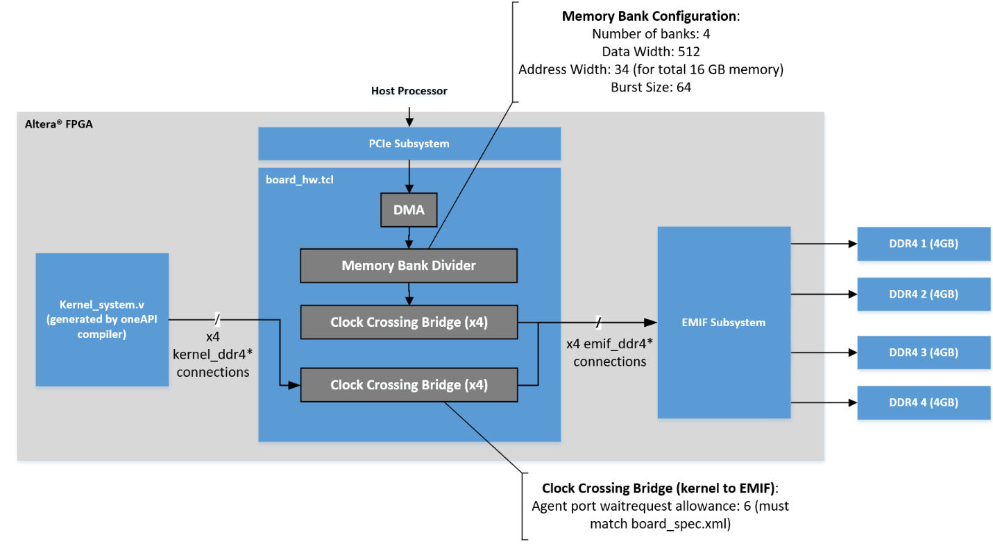
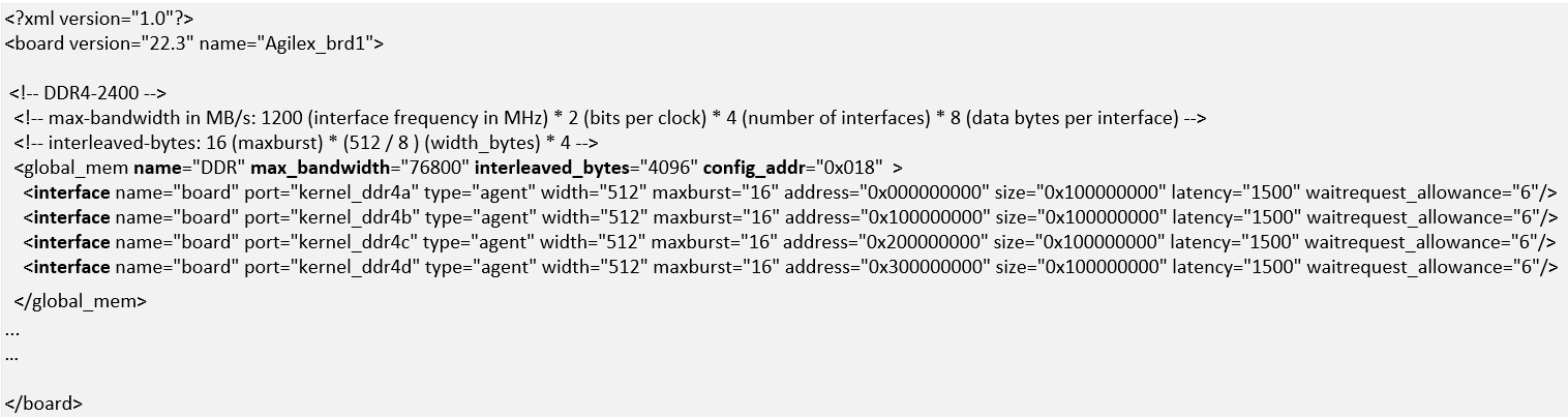
Example below shows a global_mem element configuration for a kernel system connected to four 4GB DDR4 memory banks. The DDR4 interface is 64 bit operating at 1200MHz. Note that the name of the platform designer system name is board.qsys. As mentioned in description for interleaved_bytes in table above, the Memory Bank Divider configuration ensures that the host interface matches the interleaved_bytes setting (i.e. 512 bits x 64 burst size = 4096 bytes). For information on waitrequest_allowance, refer to section 2.1.4 on interface attribute.
Note: More details on the
Memory Bank Dividerand the Clock Crossing Bridges is covered in section 3.0
Figure 2-6: Memory Connection Example Block Diagram and Corresponding global_mem Element in board_spec.xml
2.1.5.1 Global Memory Configurations
A board can have a single memory bank, multiple memory banks of the same type (e.g. 4 banks of DDR4) or different banks of different types.
The partitioning of memory for oneAPI kernel developers is explained in the Intel® oneAPI DPC++/C++ Compiler Handbook for Intel® FPGAs. The global memory configuration required by an application kernel must match the configuration in board_spec.xml as the compiler uses this information to generate a suitable architecture for the application. The different memory configurations are
- A single global memory region (possible with same type of memory banks)
- Different global memories (heterogeneous memory)
2.1.5.1.1 Contiguous Global Memory
For boards with multiple memory banks of the same type, designers can configure these as a single contiguous global memory region. This is done by specifying each memory interface within a single global_mem element. Figure 2-6 showed 4 DDR4 memory banks configured as a single global memory region.
With this configuration, FPGA application developers have the option to use contiguous memory region in an interleaved or a non-interleaved fashion. Even with contiguous memory regions, kernel developers can partition data buffers across the banks/memory channels. Please refer to Global Memory Access Optimization section in Intel® oneAPI DPC++/C++ Compiler Handbook for Intel® FPGAs for more details on these partitioning techniques.
2.1.5.1.2 Heterogeneous Memory
For boards with different memory technologies, designers must specify each type of memory that the kernel needs to access as a separate global memory.
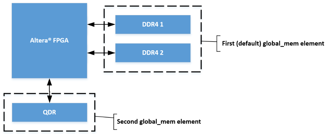
Figure 2-7 shows heterogeneous configurations and the global_mem element structure for two different types of memories (QDR, DDR4). The global_mem element in example below also demonstrates use of the default attribute. It is set to "1" for the DDR4 memory banks, indicating to the oneAPI compiler that the default global memory for the kernel is DDR4.
Figure 2-7: Heterogeneous Memory Example Block Diagram and Corresponding global_mem Element in board_spec.xml

Unified Shared Memory
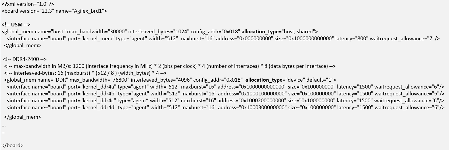
For applications that require USM support, the board_spec.xml must specify host and device memories in a heterogeneous manner.
The allocation_type must be host for global memory region on the host processor. The allocation_type must be set to device for global memory on the FPGA board.
Example below extends the board_spec.xml snippet in figure 2-6 to add a global_mem element for the kernel system to host processor memory interface.
Figure 2-8: global_mem Element Example for Unified Shared Memory(USM)
2.1.6 host Element
The host element of the board_spec.xml file provides information on the interface from the host to the kernel. Figure below shows an example of host element.
Figure 2-9: host Element Example
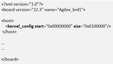
Table 2-8: Attributes for the host Element
| Attribute | Description |
|---|---|
| kernel_config | This attribute informs the oneAPI compiler at what offset the kernel resides, from the perspective of the kernel_cra host on the kernel_interface module.* start: the starting address of the kernel. Normally, this attribute has a value of 0 because the kernel_cra host should not host anything except kernels. * size: keep this parameter at the default value of 0x0100000. |
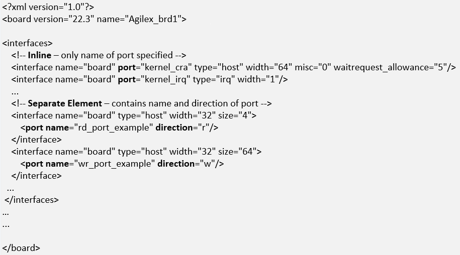
2.1.7 interfaces Element
The interfaces element of the board_spec.xml file describes the kernel interfaces that connect to application kernels and control kernel behavior. For this element, include one of each interface of types host, irq and streamsource. Refer to the interface section for the parameters you must specify for each interface.
In addition to the host, irq, and streamsource interfaces, if your design includes a separate Platform Designer subsystem containing the board logic, the kernel clock and reset interfaces exported from it are also part of the interfaces element. Specify these interfaces with the kernel_clk_reset attribute and its corresponding parameters.
Figure below shows example of interfaces element.
Figure 2-10: interfaces Element Example
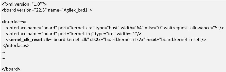
Table 2-9: Parameters for the kernel_clk_reset Attribute
| Attribute | Description |
|---|---|
| clk | The Platform Designer name for the kernel clock interface |
| clk2x | The Platform Designer name for the 2xkernel clock interface |
| reset | The Platform Designer connection for the kernel reset |
Note: Name the kernel clock and reset interfaces in the Platform Designer connection format (that is,
. ). For example: board.kernel_clk
2.1.8 channels Element
The channels element provides channels for streaming data directly between kernel and I/O. Each channel (implemented using Avalon-ST specification) must be connected to the kernel via the interface attribute. The channel interface only supports data, and valid and ready Avalon-ST signals. The I/O channel defaults to 8-bit symbols and big-endian ordering at the interface level.
Figure below shows an example of channels element for a single channel with a width of 64 bits. The chan_id attribute identified helps identify the port in the generated kernel_system. Refer to section 2.1.4 for more information about the interface attribute parameters. Additional interface attributes can be added for additional channels.
Figure 2-11: channels Element Example

For more information about kernel development using channels, refer to I/O Pipes section in Intel® oneAPI DPC++/C++ Compiler Handbook for Intel® FPGAs.
2.2 board_env.xml File
The board_env.xml file is used by the oneAPI toolkit to set up the board installation that enables the compiler to target a specific accelerator platform. The board_env.xml file must be located in the top most level of the oneAPI ASP for each platform. For example, the board_env.xml for oneAPI ASP for OFS reference platforms is located in the oneapi-asp/Platform-Name folder, where Platform-Name is n6001, fseries-dk, iseries-dk for OFS targeting Agilex® 7 FPGA and d5005 for OFS targeting Stratix® 10 FPGA.
A sample board_env.xml file is shown below. Table 2-10 explains the elements of this file.
Figure 2-12: board_env.xml File Structure
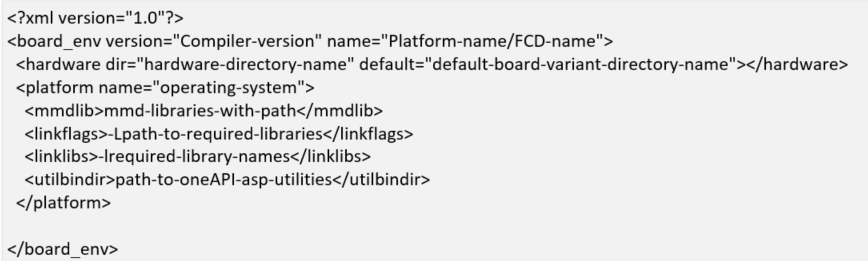
Table 2-10: Specifications of XML Elements and Attributes in the board_env.xml File
| Element | Attribute Description |
|---|---|
| board_env | * version: The oneAPI compiler version used to create oneAPI ASP * name: The runtime uses this as the name of the FPGA Client Driver(FCD) file name |
| hardware | * dir: Name of the subdirectory, within the oneAPI ASP directory, that contains the board variant directories for a platform * default: The default board variant that the compiler targets when a platform has multiple board variants and user does not specify an explicit argument using -Xstarget option |
| platform | name: Name of the operating system. A separate platform element must be specified for each supported OS for the oneAPI ASP platform |
| mmdlib | A string that specifies the path to the MMD library of your oneAPI ASP. To load multiple libraries, specify them in an ordered, comma-separated list. The host application will load the libraries in the order that they appear in the list > Note: You can use %b to reference your oneAPI ASP directory and provide path relative to oneAPI ASP directory, for example, if MMD library is located inside linux64/lib folder in oneAPI ASP, the path would be %b/linux64/lib/libintel_opae_mmd.so |
| linkflags | A string that specifies the linker flags necessary for linking with the MMD layer available with the board > Note: You can use %b to reference your oneAPI ASP directory and provide path relative to oneAPI ASP directory, for example, if MMD library is located inside linux64/lib folder in oneAPI ASP, the path would be %b/linux64/lib. |
| linklibs | A string that specifies the libraries the oneAPI runtime must link against to use the MMD layer available with the board |
| utilbindir | Directory in which the runtime expects to locate board utility executables (i.e. install, uninstall, program, diagnose, flash) > Note: You can use %b to reference your oneAPI ASP directory and provide path relative to oneAPI ASP directory, for example, if the utilities are located in linux64/libexec folder in oneAPI ASP, the path would be %b/linux64/libexec |
3.0 oneAPI ASP Hardware
The oneAPI compiler generates the kernel system interfaces based on specifications provided by the oneAPI ASP developer in the board_spec.xml file. The kernel system interfaces with the rest of the oneAPI ASP RTL as shown in figure 1-3.
Figure 1-3 shows 5 different paths, summarized below:
- Host to EMIF: Consisting of RTL to handle data transfer between host and on-board memory (e.g. DDR4)
- Host to Kernel: Consisting of RTL to handle control signals & interrupts between host and kernel
- Kernel to EMIF: Consisting of RTL to handle data transfer between kernel and on-board memory
- Kernel to Host memory: Required to support Unified Shared Memory. This requires some additional RTL to handle data transfer between kernel and host memory
- Kernel to HSSI: Consisting of RTL to handle data streaming between kernel and I/O
Please note that the kernel system generated by oneAPI compiler has Avalon® interfaces. OFS FIM has AXI interfaces. Additional logic blocks from Platform Interface Manager are used to handle protocol conversions. Please refer to section 5.3.1 for more details on PIM.
The next few sections cover some of the important IP components required to enable kernel communications with host and board peripherals. More design implementation details are covered in section 5.0.
3.1 Host to External Memory Interface(EMIF)
The host to EMIF datapath consists of a PCIe Subsytem(SS), EMIF Subsystem located in the FIM and a Direct Memory Access(DMA) engine in the oneAPI ASP.
PCIe Subsystem(SS) has the PCIe IP and additional logic to handle PCIe packet format and routing. FIM handles routing signals received from host to the user design located in a region referred to as Accelerator Functional Unit(AFU) (the Kernel system resides in the AFU).
Note: For more information about the PCIe SS, please refer to Intel FPGA IP Subsystem for PCI Express IP User Guide
The External Memory Interface Subsystem (EMIF SS) consists of EMIF IP and additional logic for handling transfers between AFU and on-board memories.
Note: For more information about the EMIF SS, please refer to Memory Subsystem Intel FPGA IP User Guide
Large buffers of data are usually transferred between host and on-board memory in oneAPI applications. This necessitates a Direct Memory Access(DMA) Engine between host and on-board memory. In oneAPI ASP designs for OFS reference platform, this DMA engine is placed in the AFU region.
As described in section 2.1.5.1, there are different configurations for memories on board. In addition to above, figure 1-3 also shows an additional IP in the host to memory datapath, called Memory Bank Divider. This IP is used for handling one of the most commonly used configurations, i.e. configuring multiple memory banks of same type as a contiguous memory region. In this case, the kernel has a contiguous view of the memory and data can be interleaved across the different memory channels. The host must also have the same view of the memory in order to ensure read and write transactions from correct addresses.
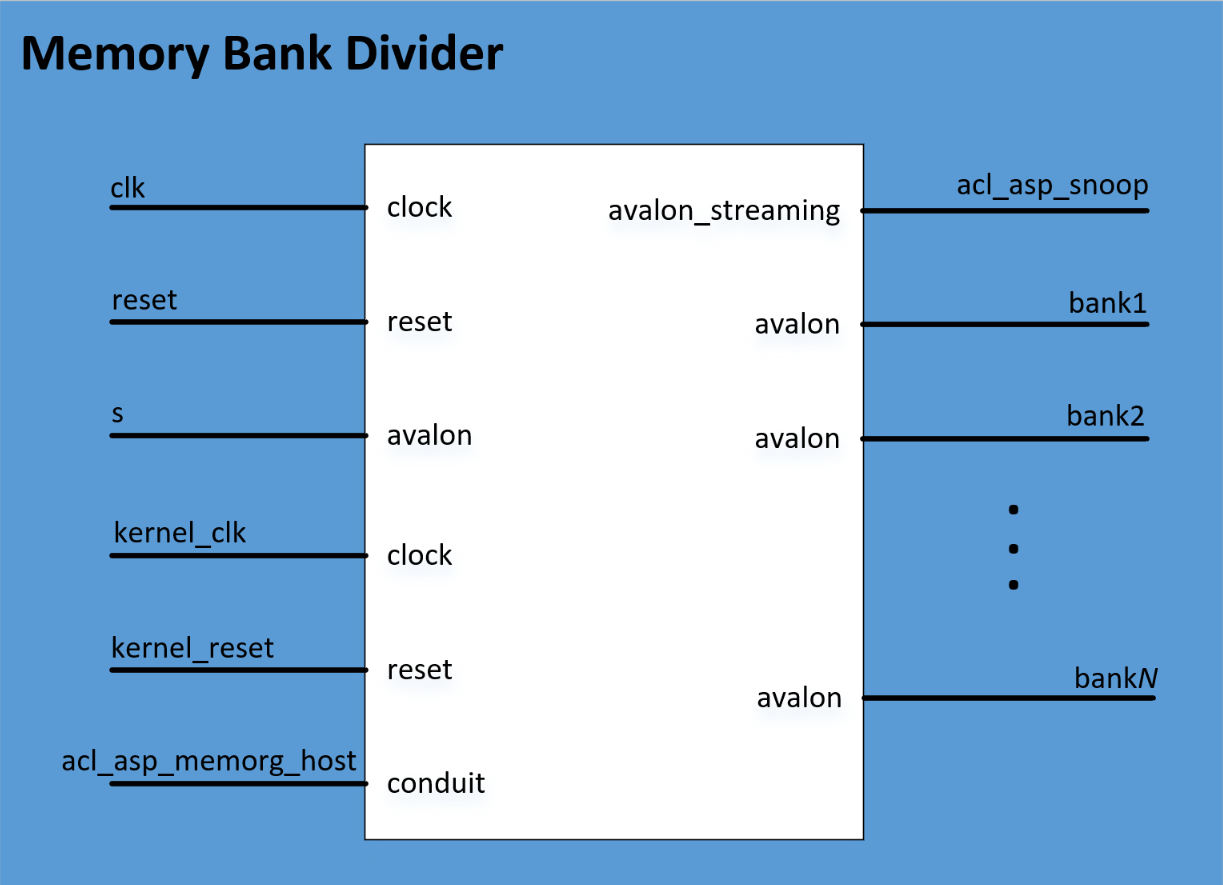
3.1.1 Memory Bank Divider
The Memory Bank Divider is a oneAPI ASP IP component that takes an incoming request from the host interface on the Avalon®-MM agent port and routes it to the appropriate bank host port. This component must reside on the path between the host and the global memory interfaces. In addition, it must reside outside of the path between the kernel and the global memory interfaces.
The following image shows the IP interfaces. Table 3-2 provides more information on the interface signals.
Figure 3-1: Memory Bank Divider IP
This IP is currently made available as part of the oneapi-asp located in oneapi-asp/common/hardware/common/build/ip folder (memory_bank_divider_hw.tcl). The IP can be instantiated in a top level system by passing values to the parameters as shown in snippet below. Table 3-1 provides more information on the parameters. The oneAPI ASP for OFS reference platforms instantiates this IP in a similar way. Refer to section 5.0 for more information on implementation details for oneAPI ASP for OFS reference platforms.
    add_instance memory_bank_divider memory_bank_divider <version>
    set_instance_parameter_value memory_bank_divider {NUM_BANKS} {number-of-memory-banks}
    set_instance_parameter_value memory_bank_divider {SEPARATE_RW_PORTS} {true/false-value}
    set_instance_parameter_value memory_bank_divider {PIPELINE_OUTPUTS} {true/false-value}
    set_instance_parameter_value memory_bank_divider {SPLIT_ON_BURSTBOUNDARY} {true/false-value}
    set_instance_parameter_value memory_bank_divider {DATA_WIDTH} {data-width}
    set_instance_parameter_value memory_bank_divider {ADDRESS_WIDTH} {total-addressable-width}
    set_instance_parameter_value memory_bank_divider {BURST_SIZE} {burst-size}
    set_instance_parameter_value memory_bank_divider {MAX_PENDING_READS} {max-pending-reads}
    set_instance_parameter_value memory_bank_divider {ASYNC_RESET} {value}
    set_instance_parameter_value memory_bank_divider {SYNCHRONIZE_RESET} {value}
Table 3-1: Parameter Settings for the Memory Bank Divider Component
| Parameter Name in IP TCL | Parameter | Description |
|---|---|---|
| NUM_BANKS | Number of banks | Number of memory banks for each of the global memory types included in your board system. A single memory bank divider has the following allowed values: 1,2,4,8 for this parameter. |
| SEPARATE_RW_PORTS | Separate read/write ports | Enable this parameter so that each bank has one port for read operation and one for write operation. |
| PIPELINE_OUTPUTS | Add pipeline stage to output | Enable this parameter to allow for potential timing improvements. |
| DATA_WIDTH | Data Width | Width of the data bus to the memory in bits. |
| ADDRESS_WIDTH | Address Width (total addressable) | Total number of address bits necessary to address all global memory. |
| BURST_SIZE | Burst size (maximum) | Set to a value equal to interleaved_bytes/(width/8), where interleaved_bytes and width are defined in the interface attribute of the global_mem element in the board_spec.xml file. |
| MAX_PENDING_READS | Maximum Pending Reads | Maximum number of pending read transfers the component can process without asserting a waitrequest signal. Recommended value is 64 if ASP has two global memory banks or fewer and 128 if ASP has four or more global memory banks. CAUTION: A high Maximum Pending Reads value causes Platform Designer to insert a deep response FIFO buffer, between the component's host and agent, that consumes a lot of device resources. It also increases the achievable bandwidth between host and memory interfaces. |
| SPLIT_ON_BURSTBOUNDARY | Split read/write bursts on burst word boundary | Enable splitting of read and write bursts on burst word boundary. Enable this parameter if the Number of banks parameter value is greater than 1, and the burst reads and writes that the host controller sends to the agent port crosses burst word boundary. |
Table 3-2: Signals and Ports for the Memory Bank Divider Component
| Signal or Port | Description |
|---|---|
| clk | The bank divider logic uses this clock input. If the IP of your host and memory interfaces have different clocks, ensure that clk clock rate is not slower than the slowest of the two IP clocks. |
| reset | The reset input that connects to the board power-on reset. |
| s | The agent port that connects to the host interface controller. |
| kernel_clk | The kernel_clk drives this clock input |
| kernel_reset | The kernel_reset output from the Kernel Interface IP drives this reset input. |
| acl_asp_snoop | Export this Avalon® Streaming (Avalon®-ST) source. In the board_spec.xml file, under interfaces, describe only the snoop interface for the default memory (acl_internal_snoop). If you have a heterogeneous memory design, perform these tasks only for the Memory Bank Divider component associated with the default memory.Important: The memory system you build in HW tcl (e.g. ddr_board_hw.tcl in oneapi-asp for OFS reference platforms. Refer to section 5 for more details on ddr_board_hw.tcl) alters the width of acl_asp_snoop. You must update the width of the streamsource interface within the channels element in the board_spec.xml file to match the width of acl_asp_snoop.In the board_spec.xml file, update the width of the snoop interface (acl_internal_snoop) specified with the streamsource kernel interface within the interfaces element. Updating the width ensures that the global_mem interface entries in board_spec.xml match the characteristics of the bankN Avalon®-MM hosts from corresponding Memory Bank Divider component for the default memory. |
| acl_asp_memorg_host | This conduit connects to the acl_asp_memorg_host interface of the Kernel Interface IP.> Note: Signal present if Number of banks > 1. |
| bank1, bank2, ..., bank8 | The number of memory hosts available in the Memory Bank Divider depends on the number of memory banks that were included when the unit was instantiated. Connect each bank with each memory interface in the same order as the starting address for the corresponding kernel memory interface specified in the board_spec.xml file. For example, global_mem interface that begins at address 0 must correspond to the memory host in bank1 from the Memory Bank Divider. |
3.2 Host to Kernel Interface
The host exchanges control signals with kernel with the help of an additional oneAPI ASP IP . The control signals coming from the host are on a different clock domain (PCIe clock) while the kernel runs on different clock frequency . The Kernel Interface IP handles the clock domain crossing for these control signals as well as handles communication with kernel CSR, interrupts and generates the reset for oneAPI kernel. All oneAPI ASP designs must instantiate Kernel Interface IPs to ensure the kernel functions correctly.
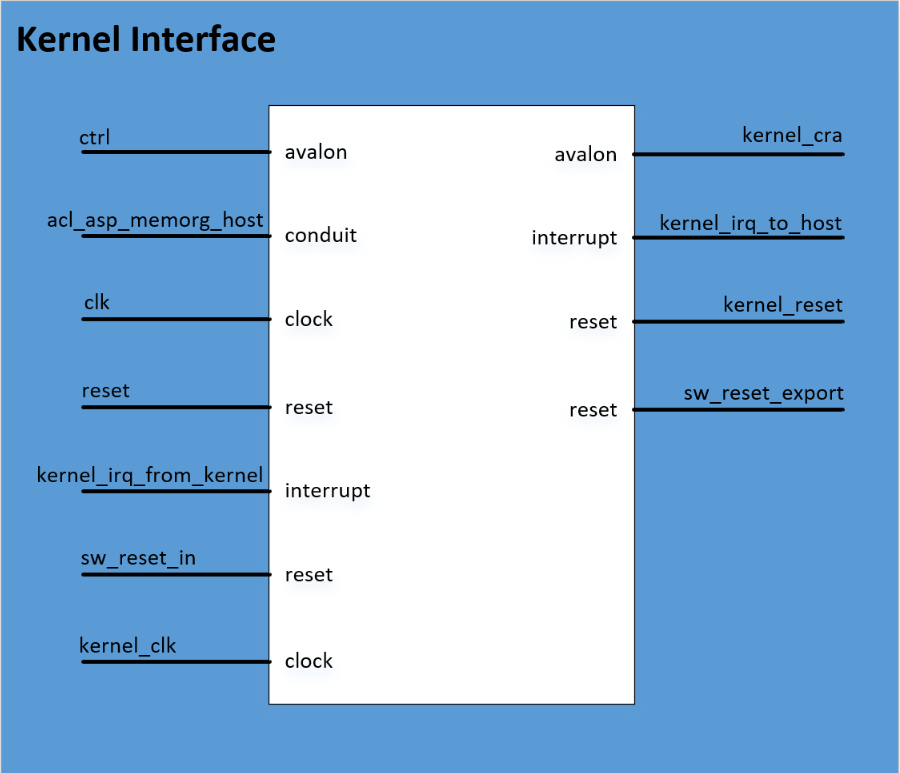
3.2.1 Kernel Interface
The Kernel Interface is an oneAPI ASP component that allows the host interface to access and control the oneAPI kernel.
The following image shows the IP interfaces. Table 3-4 provides more information on the interface signals.
Figure 3-2: Kernel Interface IP
This IP is currently made available as part of the oneapi-asp located in oneapi-asp/common/hardware/common/build/ip folder (kernel_interface_hw.tcl). The IP can be instantiated in a top level system by passing values to the parameters as shown in snippet below. Table 3-3 provides more information on the parameter. The oneAPI ASP for OFS reference platforms instantiates this IP in a similar way. Refer to section 5.0 for more information on implementation details for oneAPI ASP for OFS reference platforms.
    add_instance kernel_interface kernel_interface <version>
    set_instance_parameter_value kernel_interface {NUM_GLOBAL_MEMS} {value}
Table 3-3: Parameter Settings for the Kernel Interface Component
| Parameter Name in IP TCL | Parameter | Description |
|---|---|---|
| NUM_GLOBAL_MEMS | Number of global memory systems | Number of global memory types in your board design. |
Table 3-4: Signals and Ports for the Kernel Interface Component
| Signal or Port | Description |
|---|---|
| clk | The clock input used for the host control interface. The clock rate of clk can be slow. |
| reset | This reset input resets the control interface. It also triggers the kernel_reset signal, which resets all kernel logic. |
| ctrl | Use this agent port to connect to the host interface. This interface is a low-speed interface with which you set kernel arguments and start the kernel's execution. |
| kernel_clk | kernel clock drives this clock input. |
| kernel_cra | This Avalon®-MM host interface communicates directly with the kernels generated by the oneAPI compiler. Export the Avalon®-MM interface to the Kernel Interface and name it in the board_spec.xml file. |
| sw_reset_in | When necessary, the host interface resets the kernel via the ctrl interface. If the board design requires a kernel reset, it can do so via this reset input. Otherwise, connect the interface to a global power-on reset. |
| kernel_reset | Use this reset output to reset the kernel and any other hardware that communicates with the kernel. Warning: This reset occurs between the MMD open and close calls. Therefore, it must not reset anything necessary for the operation of your MMD. |
| sw_reset_export | This reset output is the same as kernel_reset, but it is synchronized to the clk interface. Use this output to reset logic that is not in the kernel_clk clock domain but should be reset whenever the kernel resets. |
| acl_asp_memorg_host | The memory interfaces use these signals. Based on the number of global memory systems you specify in the Kernel Interface component parameter editor, the Quartus® Prime Pro Edition Software creates the corresponding number of copies of this signal, each with a different hexadecimal suffix. Connect each signal to the Memory Bank Divider component associated with each global memory system (for example, DDR). Then, list the hexadecimal suffix in the config_addr attribute of the global_mem element in the board_spec.xml file. |
| kernel_irq_from_kernel | An interrupt input from the kernel. This signal is exported and named in the board_spec.xml file. |
| kernel_irq_to_host | An interrupt output from the kernel. This signal connects to the host interface. |
3.3 Kernel to External Memory Interface
The kernel system masters the interface from kernel to external memory. oneAPI compiler generates kernel system memory interface logic (e.g. Load-Store Unit) according to the global memory configuration and interface specifications in board_spec.xml file.
The kernel system operates at kernel clock, hence, oneAPI ASP developers must handle clock domain crossing from kernel to EMIF clock domain.
For implementation details for all datapaths discussed above, please refer to section 5.3.
4.0 oneAPI ASP Software
The software components of oneAPI ASP consist of the Memory Mapped Device(MMD) layer and the board utility routine required by runtime.
Section 4.1 introduces MMD layer and section 4.2 explains board utilities.
4.1 Memory Mapped Device(MMD) Layer
The oneAPI ASP Memory Mapped Device (MMD) layer sits in between the oneAPI runtime and OPAE SDK and provides a set of API for device communication and control. The runtime calls into the MMD API for various operations like opening a handle to the device, allocating memory etc.
Note: For more information about the FPGA runtime, please refer to FPGA Runtime documentation here.
A header file, called aocl_mmd.h, has the list of MMD API calls that must be implemented by oneAPI ASPs. From the perspective of the caller, below is typical MMD API lifecycle:
- Open device to provide handle for further operations
- Set interrupt and status handlers
- Program device with kernel bitstream
- Allocate memory if required
- Perform Read, Write operations (DMA or MMIO)
- Free memory if allocation done in step 4
- Close device. No further operations permitted until subsequent open device call
Table below summarizes all APIs listed in aocl_mmd.h.
Table 4-1: Summary of MMD API from aocl_mmd.h
| API | Purpose |
|---|---|
| aocl_mmd_get_offline_info | Obtain offline information about the board. This function is offline because it is device-independent and does not require a handle from the aocl_mmd_open() call |
| aocl_mmd_get_info | Obtain information about the board specified in the requested_info_id argument (refer to section 4.1.2 for more information) |
| aocl_mmd_open | Open and initialize the specified device |
| aocl_mmd_close | Close an opened device via its handle |
| aocl_mmd_set_interrupt_handler | Set the interrupt handler for the opened device |
| aocl_mmd_set_device_interrupt_handler | Sets the device interrupt handler for opened device, interrupt handler is called to notify runtime of any exceptions |
| aocl_mmd_set_status_handler | Set the operation status handler for the opened device |
| aocl_mmd_yield | The aocl_mmd_yield function is called when the host interface is idle. The host interface might be idle because it is waiting for the device to process certain events |
| aocl_mmd_read | Read operation on a single interface |
| aocl_mmd_write | Write operation on a single interface |
| aocl_mmd_copy | Copy operation on a single interface |
| aocl_mmd_hostchannel_create | Creates a channel interface |
| aocl_mmd_hostchannel_destroy | Destroys channel interface |
| aocl_mmd_hostchannel_get_buffer | Provides host with pointer used to read/write from channel interface |
| aocl_mmd_hostchannel_ack_buffer | Acknowledges read/write from channel |
| aocl_mmd_program | Reprogram operation for the specified device |
| aocl_mmd_host_alloc | Provide memory that is allocated on the host. Host allocations are accessible by the host and one or more devices |
| aocl_mmd_free | Free memory that has been allocated by MMD |
| aocl_mmd_device_alloc | Allocate memory that is owned by the device |
| aocl_mmd_shared_alloc | Allocate shared memory between the host and the FPGA |
| aocl_mmd_shared_migrate | Handle migration of non-concurrent shared allocations any time the accessor of the allocation changes |
Sections below cover more details for each API (expected arguments, return values). Section 5.4 discusses more about the implementation of the MMD layer APIs in oneAPI ASPs for OFS reference platforms.
4.1.1 aocl_mmd_get_offline_info
The aocl_mmd_get_offline_info function obtains offline information about the board specified in the requested_info_id argument. This function is offline because it is device-independent and does not require a handle from the aocl_mmd_open() call.
Syntax
    int aocl_mmd_get_offline_info (
        aocl_mmd_offline_info_t requested_info_id,
        size_t param_value_size,
        void* param_value,
        size_t* param_size_ret )
Function Arguments
requested_info_id: An enum value of typeaocl_mmd_offline_info_tthat indicates the offline device information returning to the caller.
Table 4-2: Possible Enum Values for the requested_info_id Argument
| Name | Description | Type |
|---|---|---|
| AOCL_MMD_VERSION | Version of MMD layer | char* |
| AOCL_MMD_NUM_BOARDS | Number of candidate boards | int |
| AOCL_MMD_BOARD_NAMES | Names of available boards > Note: Separate each board name by a semicolon (;) delimiter. |
char* |
| AOCL_MMD_VENDOR_NAME | Name of board vendor | char* |
| AOCL_MMD_VENDOR_ID | An integer board vendor ID | int |
| AOCL_MMD_USES_YIELD | A value of 0 instructs the runtime to suspend user's processes. The runtime resumes these processes after it receives an event update (for example, an interrupt) from the MMD layer. A value of 1 instructs the runtime to continuously call the aocl_mmd_yield function while it waits for events to complete.CAUTION: Setting AOCL_MMD_USES_YIELD to 1 might cause high CPU utilization if the aocl_mmd_yield function does not suspend the current thread. |
int |
-
param_value_size: Size of theparam_valuefield in bytes. This size_t value should match the size of the expected return type that the enum definition indicates. For example, ifAOCL_MMD_NUM_BOARDSreturns a value of type int, set theparam_value_sizeto sizeof (int). You should see the same number of bytes returned in theparam_size_retargument. -
param_value: A void* pointer to the variable that receives the returned information. -
param_size_ret: A pointer argument of type size_t* that receives the number of bytes of returned data.
Return Value
A negative return value indicates an error.
4.1.2 aocl_mmd_get_info
The aocl_mmd_get_info function obtains information about the board specified in the requested_info_id argument.
Syntax
    int aocl_mmd_get_info (
        int handle,
        aocl_mmd_info_t requested_info_id,
        size_t param_value_size,
        void* param_value,
        size_t* param_size_ret )
Function Arguments
-
handle: A positive int value representing the handle to the board obtained from theaocl_mmd_open()call. -
requested_info_id: An enum value of typeaocl_mmd_info_tthat indicates the device information returning to the caller.
Table 4-3: Possible Enum Values for the requested_info_id Argument
| Name | Description | Type |
|---|---|---|
| AOCL_MMD_NUM_KERNEL_INTERFACES | Number of kernel interfaces | int |
| AOCL_MMD_KERNEL_INTERFACES | Kernel interfaces | int* |
| AOCL_MMD_PLL_INTERFACES | Kernel clock handles | int* |
| AOCL_MMD_MEMORY_INTERFACE | Global memory handle | int |
| AOCL_MMD_TERMPERATURE | Temperature measurement | float |
| AOCL_MMD_PCIE_INFO | PCIe® information | char* |
| AOCL_MMD_BOARD_NAME | Board name | char* |
| AOCL_MMD_BOARD_UNIQUE_ID | Unique board ID | char* |
| AOCL_MMD_CONCURRENT_READS | Number of parallel reads A value of 1 indicates serial reads. |
int |
| AOCL_MMD_CONCURRENT_WRITES | Number of parallel writes A value of 1 indicates serial writes. |
int |
| AOCL_MMD_CONCURRENT_READS_OR_WRITES | Total number of concurrent read and write operations | int |
| AOCL_MMD_MIN_HOST_MEMORY_ALIGNMENT | Minimum alignment that the oneAPI ASP supports for host allocations | size_t |
| AOCL_MMD_HOST_MEM_CAPABILITIES | Capabilities of aocl_mmd_host_alloc() function |
unsigned int |
| AOCL_MMD_SHARED_MEM_CAPABILITIES | Capabilities of aocl_mmd_shared_alloc() function |
unsigned int |
| AOCL_MMD_DEVICE_MEM_CAPABILITIES | Capabilities of aocl_mmd_device_alloc() function |
unsigned int |
| AOCL_MMD_HOST_MEM_CONCURRENT_GRANULARITY | Granularity of concurrent host accesses | size_t |
| AOCL_MMD_SHARED_MEM_CONCURRENT_GRANULARITY | Granularity of concurrent shared accesses | size_t |
| AOCL_MMD_DEVICE_MEM_CONCURRENT_GRANULARITY | Granularity of concurrent device accesses | size_t |
-
param_value_size: Size of theparam_valuefield in bytes. This size_t value should match the size of the expected return type that the enum definition indicates. For example, if AOCL_MMD_TEMPERATURE returns a value of type float, set theparam_value_sizeto sizeof (float). You should see the same number of bytes returned in theparam_size_retargument. -
param_value: A void* pointer to the variable that receives the returned information. -
param_size_ret: A pointer argument of type size_t* that receives the number of bytes of returned data.
Capability Values
Table 4-4: Capability Values for aocl_mmd_get_info Function
| Value | Description |
|---|---|
| AOCL_MMD_MEM_CAPABILITY_SUPPORTED | If you do not set this value, allocation function is not supported even if other capabilities are set. |
| AOCL_MMD_MEM_CAPABILITY_ATOMIC | Supports atomic access to the memory by either the host or the device. |
| AOCL_MMD_MEM_CAPABILITY_CONCURRENT | Supports concurrent access to the memory either by the host or the device if the accesses are not on the same block. Block granularity is defined by AOCL_MMD_*_MEM_CONCURRENT_GRANULARITY. Blocks are aligned to this granularity. |
| AOCL_MMD_MEM_CAPABILITY_P2P | Memory can be accessed by multiple devices at the same time. |
Return Value
A negative return value indicates an error.
4.1.3 aocl_mmd_open
The aocl_mmd_open function opens and initializes the specified device.
Syntax
int aocl_mmd_open (const char *name)
Function Arguments
name: The function opens the board with a name that matches this const char* string. The name typically matches the one specified by the AOCL_MMD_BOARD_NAMES offline information.
The runtime first queries the AOCL_MMD_BOARD_NAMES offline information to identify the boards that it might be able to open. Then it attempts to open all possible devices by calling aocl_mmd_open and using each of the board names as argument.
Note: The name must be a C-style NULL-terminated ASCII string.
Return Value
If aocl_mmd_open() executes successfully, the return value is a positive integer that acts as a handle to the board.
If aocl_mmd_open() fails to execute, a negative return value indicates an error. In the event of an error, the runtime proceeds to open other known devices. Therefore, it is imperative that the MMD layer does not exit the application if an open call fails.
4.1.4 aocl_mmd_close
The aocl_mmd_close function closes an opened device via its handle.
Syntax
int aocl_mmd_close (int handle)
Function Arguments
handle: A positive int value representing the handle to the board obtained from theaocl_mmd_open()call.
Return Value
If the aocl_mmd_close() executes successfully, the return value is 0.
If aocl_mmd_close() fails to execute, a negative return value indicates an error.
4.1.5 aocl_mmd_set_interrupt_handler
The aocl_mmd_set_interrupt_handler function sets the interrupt handler for the opened device.
When the device internals identify an asynchronous kernel event (for example, a kernel completion), the interrupt handler is called to notify the runtime of the event.
Note: Ignore the interrupts from the kernel until this handler is set.
Syntax
    int aocl_mmd_set_interrupt_handler (
        int handle,
        aocl_mmd_interrupt_handler_fn fn,
        void* user_data )
Function Arguments
-
handle: A positive int value representing the handle to the board obtained from theaocl_mmd_open()call. -
fn: The callback function to invoke when a kernel interrupt occurs. Thefnargument is of typeaocl_mmd_interrupt_handler_fn, which is defined as follows:
typedef void (*aocl_mmd_interrupt_handler_fn)( int handle, void* user_data );
user_data: The void* type user-provided data that passes tofnwhen it is called.
Return Value
If the function executes successfully, the return value is 0.
If the function fails to execute, a negative return value indicates an error.
4.1.6 aocl_mmd_set_device_interrupt_handler
The aocl_mmd_set_device_interrupt_handler function sets the device interrupt handler for the opened device. When the device internals identify an asynchronous exception event (for example, a bit correction event), the device interrupt handler is called to notify the runtime of the event.
Note: Ignore the interrupts from the device until this handler is set.
Syntax
    int aocl_mmd_set_device_interrupt_handler (
        int handle,
        aocl_mmd_device_interrupt_handler_fn fn,
        void* user_data )
Function Arguments
-
handle: A positive int value representing the handle to the board obtained from theaocl_mmd_open()call. -
fn: The callback function to invoke when a kernel interrupt occurs. Thefnargument is of typeaocl_mmd_device_interrupt_handler_fn, which is defined as follows:
typedef void (*aocl_mmd_device_interrupt_handler_fn)( int handle, aocl_mmd_interrupt_info* data_in, void* user_data );
aocl_mmd_interrupt_info is defined as:
    typedef struct {
        unsigned long long int exception_type;
        void *user_private_info;
        size_t user_cb;
    } aocl_mmd_interrupt_info;
Where:
exception_typeacts as a bitfield that contains exactly one bit, corresponding to an exception number.user_private_infoanduser_cbrepresent pointers to binary data that the OpenCL implementation return. These pointers log additional information that is helpful for debugging the error.
user_data: The void* type user-provided data that passes tofnwhen it is called.
Return Value
If the function executes successfully, the return value is 0.
If the function fails to execute, a negative return value indicates an error.
4.1.7 aocl_mmd_set_status_handler
The aocl_mmd_set_status_handler function sets the operation status handler for the opened device. The operation status handler is called under the following circumstances:
- When the operation completes successfully and status is 0.
- When the operation completes with errors and status is a negative value.
Syntax
    int aocl_mmd_set_status_handler (
        int handle,
        aocl_mmd_status_handler_fn fn,
        void* user_data )
Function Arguments
-
handle: A positive int value representing the handle to the board obtained from theaocl_mmd_open()call. -
fn: The callback function to invoke when a status update occurs. Thefnargument is of typeaocl_mmd_status_handler_fn, which is defined as follows:
typedef void (*aocl_mmd_status_handler_fn)( int handle, void* user_data, aocl_mmd_op_t op, int status );
user_data: The void* type user-provided data that passes tofnwhen it is called.
Return Value
If the function executes successfully, the return value is 0.
If the function fails to execute, a negative return value indicates an error.
4.1.8 aocl_mmd_yield
The aocl_mmd_yield function is called when the host interface is idle. The host interface might be idle because it is waiting for the device to process certain events.
Syntax
int aocl_mmd_yield (int handle)
Function Arguments
handle: A positive int value representing the handle to the board obtained from theaocl_mmd_open()call.
Return Value
A nonzero return value indicates that the yield function performed work necessary for proper device functioning such as processing direct memory access (DMA) transactions.
A return value of 0 indicates that the yield function did not perform work necessary for proper device functioning.
Note: The yield function might be called continuously if it reports that it has necessary work to perform.
4.1.9 aocl_mmd_read
The aocl_mmd_read function is the read operation on a single interface.
Syntax
    int aocl_mmd_read (
        int handle,
        aocl_mmd_op_t op,
        size_t len,
        void* dst,
        int mmd_interface, size_t offset )
Function Arguments
-
handle: A positive int value representing the handle to the board obtained from theaocl_mmd_open()call. -
op: The operation object of typeaocl_mmd_op_tused to track the progress of the operation. Ifopis NULL, the call must block, and return only after the operation completes.
Note:
aocl_mmd_op_tis defined as follows:
typedef void* aocl_mmd_op_t;
-
len: The size of the data, in bytes, that the function transfers. Declarelenwith type size_t. -
dst: The host buffer, of type void*, to which data is written. -
mmd_interface: the handle to the interface being accessed. For example, to access global memory this handle will be value obtained fromaocl_mmd_get_infocall with AOCL_MMD_MEMORY_INTERFACE asrequested_info_idargument. -
offset: The size_t byte offset within the interface at which the data transfer begins.
Return Value
If the read operation is successful, the return value is 0.
If the read operation fails, a negative return value indicates an error.
4.1.10 aocl_mmd_write
The aocl_mmd_write function is the write operation on a single interface.
Syntax
    int aocl_mmd_write (
        int handle,
        aocl_mmd_op_t op,
        size_t len,
        const void* src,
        int mmd_interface, size_t offset )
Function Arguments
-
handle: A positive int value representing the handle to the board obtained from theaocl_mmd_open()call. -
op: The operation object of typeaocl_mmd_op_tused to track the progress of the operation. Ifopis NULL, the call must block, and return only after the operation completes.
Note:
aocl_mmd_op_tis defined as follows:
typedef void* aocl_mmd_op_t;
-
len: The size of the data, in bytes, that the function transfers. Declarelenwith type size_t. -
src: The host buffer, of type const void*, from which data is read. -
mmd_interface: the handle to the interface being accessed. For example, to access global memory this handle will be value obtained fromaocl_mmd_get_infocall with AOCL_MMD_MEMORY_INTERFACE asrequested_info_idargument. -
offset: The size_t byte offset within the interface at which the data transfer begins.
Return Value
If the write operation is successful, the return value is 0.
If the write operation fails, a negative return value indicates an error.
4.1.11 aocl_mmd_copy
The aocl_mmd_copy function is the copy operation on a single interface.
Syntax
    int aocl_mmd_copy (
        int handle,
        aocl_mmd_op_t op,
        size_t len,
        int mmd_interface, size_t src_offset, size_t dst_offset )
Function Arguments
-
handle: A positive int value representing the handle to the board obtained from theaocl_mmd_open()call. -
op: The operation object of typeaocl_mmd_op_tused to track the progress of the operation. Ifopis NULL, the call must block, and return only after the operation completes.
Note:
aocl_mmd_op_tis defined as follows:
typedef void* aocl_mmd_op_t;
-
len: The size of the data, in bytes, that the function transfers. Declarelenwith type size_t. -
mmd_interface: the handle to the interface being accessed. For example, to access global memory this handle will be value obtained fromaocl_mmd_get_infocall with AOCL_MMD_MEMORY_INTERFACE asrequested_info_idargument. -
src_offset: The size_t byte offset within the source interface at which the data transfer begins. -
dst_offset: The size_t byte offset within the destination interface at which the data transfer begins
Return Value
If the copy operation is successful, the return value is 0.
If the copy operation fails, a negative return value indicates an error.
4.1.12 aocl_mmd_hostchannel_create
The aocl_mmd_hostchannel_create function creates a channel interface.
Syntax
    int aocl_mmd_hostchannel_create (
        int handle,
        char *channel_name,
        size_t queue_depth,
        int direction )
Function Arguments
-
handle: A positive int value representing the handle to the board obtained from theaocl_mmd_open()call. -
channel_name: Name of the channel to be initialized. The channel name is same as that used in theboard_spec.xmlfile. -
queue_depth: The size of pinned internal buffer in bytes. Pointer to the internal buffer is provided when the user calls theaocl_mmd_hostchannel_get_buffer()function. -
direction: The direction of the channel.
Return Value
If the function executes successfully, the return value is positive and is handle to the channel.
If the function fails to execute, a negative return value indicates an error.
4.1.13 aocl_mmd_hostchannel_destroy
The aocl_mmd_hostchannel_destroy function destroys the channel interface.
Syntax
    int aocl_mmd_hostchannel_destroy (
        int handle,
        int channel )
Function Arguments
-
handle: A positive int value representing the handle to the board obtained from theaocl_mmd_open()call. -
channel: A positive int value representing handle to the channel to close obtained from theaocl_mmd_hostchannel_create()call.
Return Value
If the function executes successfully, the return value is 0.
If the function fails to execute, a negative return value indicates an error.
4.1.14 aocl_mmd_hostchannel_get_buffer
The aocl_mmd_hostchannel_get_buffer function provides a host with a pointer to the buffer they can access to write or read from the channel interface, along with the space or data available in the buffer, in bytes.
Syntax
    void *aocl_mmd_hostchannel_get_buffer (
        int handle,
        int channel,
        size_t *buffer_size,
        int *status )
Function Arguments
-
handle: A positive int value representing the handle to the board obtained from theaocl_mmd_open()call. -
channel: A positive int value representing handle to the channel to close obtained from theaocl_mmd_hostchannel_create()call. -
buffer_size: A pointer to size_t that the function writes available buffer space or size to. -
status: A pointer to int that the function writes result of the call to.
Return Value
If the function executes successfully, int pointed to by the status pointer is 0. Returned void* may still be NULL, in which case size_t pointed by the buffer_size is 0.
If the function fails to execute, int pointed by the status pointer is a negative value.
4.1.15 aocl_mmd_hostchannel_ack_buffer
You can acknowledge write or read from the channel by calling aocl_mmd_hostchannel_ack_buffer.
Syntax
    size_t aocl_mmd_hostchannel_ack_buffer (
        int handle,
        int channel,
        size_t send_size,
        int *status )
Function Arguments
-
handle: A positive int value representing the handle to the board obtained from theaocl_mmd_open()call. -
channel: A positive int value representing handle to the channel to close obtained from theaocl_mmd_hostchannel_create()call. -
send_size: The size in bytes that the user is acknowledging. -
status: A pointer to int that the function writes result of the call to.
Return Value
If the function executes successfully, int pointed to by status pointer is 0. Also, there is no guarantee that the user's send_size is the actual size that gets acknowledged. The returned size_t is the amount of bytes that was actually acknowledged.
If the function fails to execute, int pointed by status pointer is a negative value.
4.1.16 aocl_mmd_program
The aocl_mmd_program function is the program operation for the specified device. The host must guarantee that no other operations are executing on the device during the program operation.
During aocl_mmd_program execution, the kernels are idle and no read, write, or copy operation can occur.
Disable interrupts and program the FPGA with the data from user_data, which has a size specified by the size argument. The host then calls aocl_mmd_set_status_handler and aocl_mmd_set_interrupt_handler again, which enable the interrupts. If events such as interrupts occur during aocl_mmd_program execution, race conditions or data corruption might occur.
Syntax
 int aocl_mmd_program (
    int handle,
    void * user_data,
    size_t size,
    aocl_mmd_program_mode_t program_mode )
Function Arguments
-
handle: A positive int value representing the handle to the board obtained from theaocl_mmd_open()call. -
user_data: The void* type binary contents of the fpga.bin file that is created during kernel compilation. -
size: The size ofuser_datain bytes. The size argument is of size_t. -
program_mode: The bit-field that specifies the mode of device programming.
Table 4-5: Possible Values for the program_mode Argument
program_mode Argument Value |
Description |
|---|---|
| AOCL_MMD_PROGRAM_PRESERVE_GLOBAL_MEMORY | This flag specifies that during programming the global memory on the devices are preserved. |
Return Value
If aocl_mmd_program executes successfully, the return value is the pointer value that the host uses to access shared memory.
4.1.17 aocl_mmd_host_alloc
Host allocations provide memory that is allocated on the host. This memory must be deallocated with the aocl_mmd_free function. Host allocations are accessible by the host and one or more devices. The same pointer to a host allocation may be used on the host and all supported devices. They have address equivalence.
Syntax
Once the device has signaled completion through the aocl_mmd_interrupt_handler_fn function, the host can assume it has access to the latest contents of the memory, allocated by the aocl_mmd_host_alloc function call.
    void* aocl_mmd_host_alloc (
        int* handles,
        size_t num_devices,
        size_t size,
        size_t alignment,
        aocl_mmd_mem_properties_t *properties,
        int* error )
Function Arguments
-
handles: Handles for devices that needs access to this memory. -
num_devices: Number of devices in the handles. -
size: The size of the memory region. -
alignment: The alignment (in bytes) of the allocation. -
properties: Specifies additional information about the allocated memory, described by a property type name and its corresponding value. Each property type name is immediately followed by the corresponding desired value. The list is terminated with a zero. For example, [, , , , 0] -
error: The error code defined by AOCL_MMD_ERROR*:
- AOCL_MMD_ERROR_SUCCESS: No error occurred.
- AOCL_MMD_ERROR_INVALID_HANDLE: The device handle provided is invalid.
- AOCL_MMD_ERROR_OUT_OF_MEMORY: Ran out of memory.
- AOCL_MMD_ERROR_UNSUPPORTED_ALIGNMENT: The device does not support the provided alignment.
- AOCL_MMD_ERROR_UNSUPPORTED_PROPERTY: The device does not support the provided property.
Return Value
If the aocl_mmd_host_alloc function executes successfully, the return value is a valid pointer value. Otherwise, the return value is NULL.
4.1.18 aocl_mmd_free
Releases memory that was allocated by MMD.
Syntax
int aocl_mmd_free (void* mem)
Function Arguments
mem: The pointer to the memory region. Must be a pointer that is allocated by the MMD.
Return Value
Returns one of the following error code:
- AOCL_MMD_ERROR_SUCCESS: No error occurred
- AOCL_MMD_ERROR_INVALID_POINTER: Invalid pointer provided
4.1.19 aocl_mmd_device_alloc
Allocate memory that is owned by the device. This pointer can only be accessed by the kernel. It cannot be accessed by the host. The host is able to manipulate the pointer (for example, increment it) and not just access the underlying data. This memory must be deallocated by the aocl_mmd_free() function.
Syntax
    void * aocl_mmd_device_alloc (
        int handle,
        size_t size,
        size_t alignment,
        aocl_mmd_mem_properties_t *properties,
        int* error )
Function Arguments
-
handle: Device that has access to this memory. -
size: The size of the memory region. -
alignment: The alignment (in bytes) of the memory region. -
properties: Specifies additional information about the allocated memory, described by a property type name and its corresponding value. Each property type name is immediately followed by the corresponding desired value. The list is terminated with a zero. For example, [, , , , 0]
Return Value
Returns one of the following error code:
- AOCL_MMD_ERROR_SUCCESS: No error occurred
- AOCL_MMD_ERROR_INVALID_HANDLE: The device handle provided is invalid.
- AOCL_MMD_ERROR_OUT_OF_MEMORY: Ran out of memory.
- AOCL_MMD_ERROR_UNSUPPORTED_ALIGNMENT: The device does not support the provided alignment.
- AOCL_MMD_ERROR_UNSUPPORTED_PROPERTY: The device does not support the provided property.
4.1.20 aocl_mmd_shared_alloc
Shared allocations can migrate between the host and one or more associated device. The same pointer to a shared allocation can be used on the host and the supported device. They have address equivalence.
Syntax
    void * aocl_mmd_shared_alloc (
        int handle,
        size_t size,
        size_t alignment,
        aocl_mmd_mem_properties_t* properties,
        int* error )
Function Arguments
-
handle: Device that needs access to this memory. -
size: The size of the memory region. -
alignment: The alignment (in bytes) of the allocation. -
properties: Specifies additional information about the allocated memory described by a property type name and its corresponding value. Each property type name is immediately followed by the corresponding desired value. The list is terminated with a zero. For example, [, , , , 0] -
error: The error code defined by AOCL_MMD_ERROR*.
- AOCL_MMD_ERROR_SUCCESS: No error occurred.
- AOCL_MMD_ERROR_INVALID_HANDLE: The device handle provided is invalid.
- AOCL_MMD_ERROR_OUT_OF_MEMORY: Ran out of memory.
- AOCL_MMD_ERROR_UNSUPPORTED_ALIGNMENT: The device does not support the provided alignment.
- AOCL_MMD_ERROR_UNSUPPORTED_PROPERTY: The device does not support the provided property.
Return Value
If the aocl_mmd_shared_alloc function executes successfully, the return value is a valid pointer value. Otherwise, the return value is NULL.
4.1.21 aocl_mmd_shared_migrate
A call to the aocl_mmd_shared_migrate() function must be made for non-concurrent shared allocations any time the accessor of the allocation changes. For example, the aocl_mmd_shared_migrate() function should be called indicating that the allocation should be migrated to the device before a kernel accessing the allocation is launched on the device. Similarly, the aocl_mmd_shared_migrate() function should be called indicating that the allocation is migrated to the host before the host accesses the memory after kernel completion. For concurrent allocations, this call may be used as a performance hint, but it is not strictly required for functionality.
Syntax
    int aocl_mmd_shared_migrate (
        int handle,
        void* shared_ptr,
        size_t size,
        aocl_mmd_migrate_t destination )
Function Arguments
-
handle: Device that has access to this memory. -
shared_ptr: Pointer allocated by theaocl_mmd_shared_alloc()function. -
size: Size (in bytes) of the migration. Must be a multiple of a page boundary that the oneAPI ASP supports. -
destination: The destination of the migration.
Return Value
Returns one of the following error code:
- AOCL_MMD_ERROR_SUCCESS: No error occurred.
- AOCL_MMD_ERROR_INVALID_HANDLE: The device handle provided is invalid.
- AOCL_MMD_ERROR_INVALID_MIGRATION_SIZE: The migration size is not supported by the device.
4.2 Board Utilities
oneAPI runtime provides a set of options for the aocl utility.
Note:
aoclis an utility available in the oneAPI runtime environment, please useaocl helpcommand for more information on this.
Table 4-6 shows the subcommands that aocl utility provides for FPGA platforms.
Table 4-6: aocl Board Utilities
| Subcommand | Description | Executable Call |
|---|---|---|
| install | Install board into the host system. This installs the FPGA Client Driver (FCD) for your FPGA platform. FCD allows runtime to find and load the FPGA platform libraries at runtime | aocl install path-to-FPGA-platform-oneapi-asp |
| uninstall | Uninstall board from the host system. Removes FCD. | aocl uninstall path-to-FPGA-platform-oneapi-asp |
| initialize | Configure a default FPGA image onto the board. For more information about initialization refer to Intel® oneAPI DPC++/C++ Compiler Handbook for Intel® FPGAs | Two methods are available to initalize the board: 1. aocl initialize device-name board-variant2. aocl initialize device-name oneAPI fat binary> Note: The second option requires oneAPI Base Toolkit (Base Kit) version 2024.0 & above as well as 2023.3 OFS Release for oneAPI Accelerator Support Package and above |
| program | Configure a new FPGA image onto the board | aocl program device-name aocx file |
| diagnose | Runs ICD and FCD diagnostics followed by querying devices in installed platforms. If a device-name is specified in the call, it run board vendor's test program for the FPGA platform |
* aocl diagnose : This queries the devices in FPGA platform and supplies a list of valid strings assigned to the list of devices * aocl diagnose device-name : This runs full diagnostic test on the FPGA platform |
The runtime expects the routine for each of this utilities to be defined in the oneAPI ASP. It looks for the routine executables in the location specified by the utilbinder element in the board_env.xml file.
install
oneAPI runtime uses the information in board_env.xml file to create a FCD file. The FCD file name matches name attribute of board_env element and the FCD contents are the platform libraries specified in mmdlib element. Refer to section 2.2 for more information about board_env.xml file. The runtime adds the installed platform to the list of installed packages(file used by runtime to track installed platforms) and then invokes the install routine from oneAPI ASP.
uninstall
oneAPI runtime removes the FCD file and removes the platform from list of installed packages. It then invokes the uninstall routine for oneAPI ASP.
initialize
oneAPI runtime invokes initialize routine provided by oneAPI ASPs for installed platforms.
program
oneAPI runtime loads the programming file on the FPGA by invoking program routine provided by the oneAPI ASPs for the installed platform.
diagnose
oneAPI runtime runs ICD and FCD diagnostics to check the ICD and FCD files installed on the system. It then queries for available boards in the installed platform and lists boards matching every installed platform. If a device-name is specified in the call, runtime invokes the diagnostic routine provided in oneAPI ASP.
For more information about the implementation of these routines in oneAPI ASPs for OFS reference platforms, please refer to section 5.5.
5.0 oneapi-asp Implementation Details
oneapi-asp in the OFS has four reference platform releases, one is based on Stratix® 10 FPGA and the other three are based on Agilex® 7 FPGA.
This chapter aims to explain the architecture and current implementation details of oneapi-asp for these platforms. The oneapi-asp repository is located here.
The next section explains the oneapi-asp directory structure, followed by sections on hardware and MMD layers.
5.1 oneapi-asp Directory Structure
As described in section 2.0, oneAPI compiler & runtime use the board_env.xml and board_spec.xml files to get information about the FPGA platform. The compiler expects the board_env.xml file to be at the topmost level in the platform directory. The board_env.xml file describes the location of the hardware files & platform libraries.
    <?xml version="1.0"?>
    <board_env version="Compiler-version" name="ofs_Platform-name/FCD-name">
      <hardware dir="hardware" default="Board-Variant-1"></hardware>
      <platform name="linux64">
        <mmdlib>libopae-c.so,%b/linux64/lib/libMPF.so,%b/linux64/lib/libintel_opae_mmd.so</mmdlib>
        <linkflags>-L%a/linux64/lib -L%b/linux64/lib</linkflags>
        <linklibs>-lintel_opae_mmd -lrt -lMP</linklibs>
        <utilbindir>%b/linux64/libexec</utilbindir>
      </platform>

    </board_env>
Snippet above shows a sample board_env.xml file, the corresponding oneAPI ASP directory structure must match the following format. Table 5-1 provides details on each folder.
In addition to below folders, oneAPI ASP for OFS reference platforms have another folder called commmon (oneapi-asp/common) containing the hardware files common across all reference platforms (oneapi-asp/common/hardware) and source code for the software layer, i.e. MMD & board utilities ( oneapi-asp/common/source). This is because the software layer is compatible with both Stratix® 10 FPGA and Agilex® 7 FPGA PCIe attach reference platform ASPs.
    oneapi-asp/Platform-Name/
    |--hardware/
    |--|--Board-Variant-1/
    |--|--Board-Variant-2/
    |--linux64/
    |--board_env.xml
Note:
In addition to above folders, oneAPI ASPs for OFS reference platforms have additional directories calledscripts(inoneapi-asp/commonandoneapi-asp/Platform-Name) which contains helper scripts for platform generation andoneapi-asp/common/bringupfolder which contains a sample for board bring up. Please refer to the README for each reference platform in the oneASP-asp repository for more information on these additional folders.
* README foroneapi-asptargeting Intel® FPGA PAC D5005 reference platform: README
* README foroneapi-asptargeting Intel® FPGA SmartNIC N6001-PL reference platform: README
* README foroneapi-asptargeting Agilex® 7 FPGA F-Series Development Kit (2x F-Tile):README
* README foroneapi-asptargeting Agilex® 7 FPGA I-Series Development Kit (2x R-Tile and 1xF-Tile): README
The Platform-Name is used for identifying the platform and can be alphanumeric value decided by the platform developer. For example, Platform-Name d5005 is used for oneapi-asp for Stratix® 10 FPGA as the reference platform is Intel® FPGA PAC D5005.
Table 5-1: Directory Contents
Files/Folder (path relative to oneapi-asp/Platform-Name/) |
Description |
|---|---|
hardware |
Contains hardware files (RTL, platform designer files, SDCs, compilation scripts, floorplan settings) and the board_spec.xml files for each board variants. See table 5-2 for more details |
../common/source |
Source code for MMD layer as well as oneapi-asp board utilities |
linux64 |
Location for FPGA platform libraries and executables for oneapi-asp board utilities > Note: The linux64 folder does not exist in the Platform-Name directory, it is added after the oneapi-asp build flow is complete |
board_env.xml |
Contains platform installation information. Please refer to section 2.2 for more details on board_env.xml elements |
Tables 5-2 to 5-4 give more details on each of these folders for oneAPI ASPs for OFS reference platforms (before oneapi-asp build flow unless noted otherwise, for more information about oneapi-asp build flow refer to section 5.2).
5.1.1 hardware Folder
oneapi-asp/
|--common
|--|--hardware/
|--Platform-Name
|--|--hardware/
|--|--|--common/
|--|--|--|--build
|--|--|--board-variant-1/
|--|--|--|--build
|--|--|--|--board_spec.xml
|--|--|--|--part-number_dm.xml (Please see note for this file in table 5-2)
Table 5-2: hardware Folder Contents
Files/Folder (path relative to oneapi-asp/) |
Description |
|---|---|
common/hardware |
Contains hardware design files common to all reference platforms including Quartus® software Settings Files (*.qsf), IP files, common RTL code (*.v, *.sv) as well as scripts to control compile flow |
Platform-Name/hardware/common/build |
Contains platform specific hardware design files (common to each board variant for a platform) including *.sv, *.sdc, Quartus® software ini settings file as well as scripts to control compile flow |
Platform-Name/hardware/board-variant-1/build |
Contains board variant specific hardware design files like variant specific Verilog header file (*.vh), oneapi_afu.json, *.tcl |
Platform-Name/hardware/board-variant-1/board_spec.xml |
Defines compile flow, global memory, kernel interfaces. Please see section 2.1 for more information about board_spec.xml file |
Platform-Name/hardware/board-variant-1/part-number_dm.xml |
Device Model file for Altera® FPGA part on the target platform. The name must be of the format part-number_dm.xml. This file has the total resources available on the device. > Note: The device model files provided as part of the oneAPI Base Toolkit (Base Kit) installation are located in $INTELFPGAOCLSDKROOT/share/models/dm, where INTELFPGAOCLSDKROOT is set by the setvars.sh environment setup script provided by oneAPI toolkit. If the device model file for your part number is not included in $INTELFPGAOCLSDKROOT/share/models/dm, it must be created and placed in the same folder as board_spec.xml. In oneapi-asp for reference platforms, this file only exists for platforms whose target device model files are not provided by oneAPI Base Toolkit (Base Kit) installation. |
5.1.2 common/source Folder
oneapi-asp/common/source/
|--cmake/
|--|--modules
|--extra/
|--|--intel-fpga-bbb
|--host
|--include
|--util
|--CMakeLists.txt
Table 5-3: oneapi-asp/common/source Folder Contents
| Files/Folder | Description |
|---|---|
cmake/modules |
Contains Find***.cmake files to find packages required for building MMD library |
extra/intel-fpga-bbb |
oneAPI ASP for OFS reference platforms uses a library provided as part of Intel® FPGA Basic Building Blocks (BBB) repository. The oneapi-asp build scripts clone this repository in extra directory by default |
host |
Source code for MMD API |
include |
Contains MMD header files |
util |
Contains source code for oneapi-asp reference platform routines for diagnose and program utilities |
CMakeLists.txt |
Top-level CMakeLists.txt file for building MMD and other libraries required by oneapi-asp as well as the executables for diagnose and program utilities |
5.1.3 linux64 Folder
oneapi-asp/Platform-Name/linux64/
|--include (see note below)
|--lib
|--libexec
Note: The
linux64folder does not exist in thePlatform-Namedirectory, it is present in theoneapi-asp/commonfolder as the utilities are common for all reference platforms. Theincludeandlibfolders also do not exist in theoneapi-asprepository. These along with the utilities are added to theoneapi-asp/Platform-Namefolder after theoneapi-aspbuild flow is complete.
Table 5-4: linux64 Folder Contents
| Files/Folder | Description |
|---|---|
include |
Contains header files from Intel® FPGA BBB required by MMD (see section 5.4 for more information on use of MPF from Intel® FPGA BBB in MMD) |
lib |
Contains MMD and Intel® FPGA BBB libraries |
libexec |
Contains executables/scripts for oneapi-asp board utilities |
5.2 oneapi-asp Build Flow
Figure 1-3 shows a high level overview of the hardware design and Figure 1-4 shows oneAPI ASP as part of the Open FPGA Stack. As shown in these images, all oneapi-asp hardware components reside in the AFU region in the PR slot.
Note: The architecture of the FIM with PR slot is explained in the FIM technical reference manuals, please refer to section 1.3 for links to the manuals.
The oneapi-asp repository contains source files for components that reside in the AFU region for each reference platform. oneapi-asp expects a compiled FIM netlist and a corresponding PR tree. The FIM database is copied to the oneapi-asp during ASP build flow (oneapi-asp/Platform-Name/scripts/build-asp.sh) and ASP compile scripts import the FIM database during oneAPI kernel compilation.
Notes:
1. FIM developer guide outlines steps to compile a FIM and generate PR tree, please refer to section 1.3 for links to FIM developer guides
2. The steps to buildoneapi-aspusing PR tree andbuild-asp.shscript are covered in the oneAPI Accelerator Support Package (ASP): Getting Started User Guide
The following figure shows the oneapi-asp build process.
Figure 5-1: oneapi-asp Build Flow
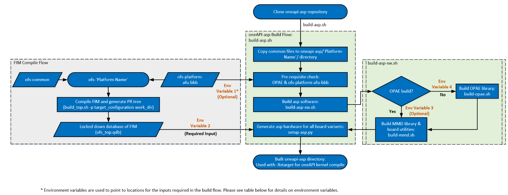
Table 5-5 Environment Variables used in Build Flow
| Variable Number | Environment Variable | Description |
|---|---|---|
| 1 | OFS_PLATFORM_AFU_BBB | Should point to location where ofs-platform-afu-bbb repository is cloned, if this variable is not set, build-asp.sh script clones the repository |
| 2 | OPAE_PLATFORM_ROOT | Must point to the PR tree generated during FIM build, this is a required variable and build flow fails without this |
| 3 | LIBOPAE_C_ROOT | Should point to the installation location for OPAE libraries (please see oneAPI Accelerator Support Package (ASP): Getting Started User Guide for more information on this variable setting), build-opae.sh script is used to clone & build OPAE library if this variable is not set. |
| 4 | OPAE_SDK_REPO_BRANCH | If LIBOPAE_C_ROOT is not set, it is recommended to set this variable to indicate the OPAE SDK branch to be used for building OPAE libraries.> Note: build-opae.sh always clones the master branch if OPAE_SDK_REPO_BRANCH environment variable is not set. If you do not have the OPAE SDK installed, please ensure the OPAE_SDK_REPO_BRANCH is set to point to the OPAE release tag matching the release notes for the OFS release you are using. Please refer to oneAPI Accelerator Support Package (ASP): Getting Started User Guide for more information on environment variable and build steps |
The scripts required for oneapi-asp build that are common to all OFS reference platforms are located in oneapi-asp/common/scripts and build scripts specific to individual platforms are located in oneapi-asp/Platform-Name/scripts folders in the oneapi-asp repository, where Platform-Name is:
n6001for Intel® FPGA SmartNIC N6001-PL reference platformd5005for Intel® FPGA PAC D5005 reference platformfseries-dkfor Agilex® 7 FPGA F-Series Development Kit (2x F-Tile)iseries-dkfor Agilex® 7 FPGA I-Series Development Kit (2x R-Tile and 1xF-Tile)
The build flow copies the scripts from oneapi-asp/common/scripts into the oneapi-asp/Platform-Name/scripts directory and generates the complete hardware directories for all board variants in oneapi-asp.
Note: For more information about the build scripts, please refer to README in
oneapi-asp/common/scriptsdirectory.
5.3 oneapi-asp Hardware Implementation
This section goes deeper into the current hardware architecture of the oneapi-asp.
Figure 1-3 shows a high level overview of the hardware design. OFS reference platforms have different board variants enabling the different paths shown in Figure 1-3. Table below summarizes the board variants and paths enabled in the oneAPI ASP reference design for each. The Path numbers in the table match the ones in Figure 1-3. Figure 5-2 to 5-5 show the detailed diagram for oneapi-asp components in each of these board variants.
Table 5-6: OFS Reference Platform Board Variants
| # | Device | Board Variant | Host to EMIF with DMA Engine (Path 1) | Host to Kernel Interface (Path 2) | Kernel to EMIF (Path 3) | Kernel to Unified Shared Memory (Path 4) | Kernel to HSSI (Path 5) | Figure # |
|---|---|---|---|---|---|---|---|---|
| 1 | Agilex® 7 FPGA Stratix® 10 FPGA |
oneapi-asp for Agilex® 7 FPGA : * ofs_n6001 * ofs_fseries-dk * ofs_iseries-dk oneapi-asp for Stratix® 10 FPGA : * ofs_d5005 |
Yes | Yes | Yes | No | No | 5-2 |
| 2 | Agilex® 7 FPGA Stratix® 10 FPGA |
oneapi-asp for Agilex® 7 FPGA : * ofs_n6001_usm * ofs_fseries-dk_usm * ofs_iseries-dk_usm oneapi-asp for Stratix® 10 FPGA : * ofs_d5005_usm |
Yes | Yes | Yes | Yes | No | 5-3 |
| 3 | Agilex® 7 FPGA | oneapi-asp for Agilex® 7 FPGA : * ofs_n6001_iopies |
Yes | Yes | Yes | No | Yes | 5-4 |
| 4 | Agilex® 7 FPGA | oneapi-asp for Agilex® 7 FPGA : * ofs_n6001_usm_iopipes |
Yes | Yes | Yes | Yes | Yes | 5-5 |
Note: Please see
oneapi-asp/Platform-Name/hardwarefolder for the board variants for each OFS reference platform.
Figure 5-2: oneapi-asp Reference Platform Hardware Design - Board Variant #1

Figure 5-3: oneapi-asp Reference Platform with USM Hardware Design - Board Variant #2

Figure 5-4: oneapi-asp Reference Platform with IO Pipes Hardware Design - Board Variant #3

Figure 5-5: oneapi-asp Reference Platform with IO Pipes and USM Hardware Design - Board Variant #4
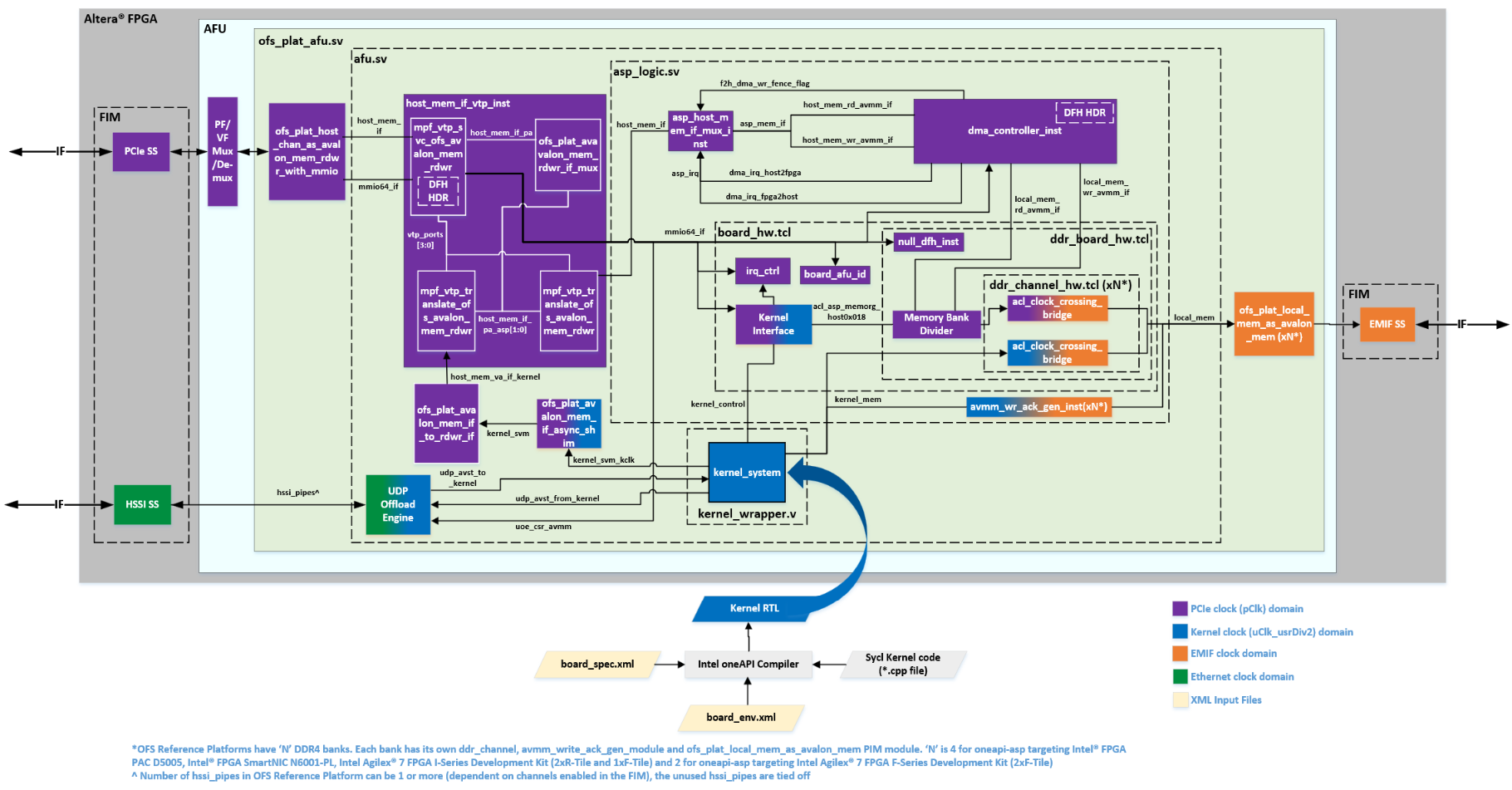
The ofs_plat_afu.sv is the top level entity for the oneapi-asp.
Hardware design files that are common for all OFS reference platforms (for the components inside ofs_plat_afu module) are located in oneapi-asp/common/hardware/common/build and hardware design file specific to the individual platforms are located in the oneapi-asp/Platform-Name/hardware/Board-Variant/build directory. The common files are copied to the oneapi-asp/Platform-Name/hardware/Board-Variant folder during oneapi-asp build flow. The FIM database files imported during oneapi-asp build (section 5.2) are located in oneapi-asp/Platform-Name/hardware/Board-Variant/fim_platform directory.
Tables 5-7 give a brief description of the important design files in all board variants, the location for these files shown in table 5-7 is post oneapi-asp build flow.
Table 5-7: Hardware Design Files in oneapi-asp/Platform-Name/hardware/Board-Variant/build
| Files/Folder | Description |
|---|---|
| afu_ip.qsf | Adds platform specific settings & design files, this file is sourced in the oneapi-asp revision being compiled (e.g.afu_flat.qsf) |
| mpf_vtp.qsf | Adds IP components from Intel® FPGA BBB (see section 5.3.2 below for information about use of MPF blocks from Intel® FPGA BBB) repository used in the design |
| asp_design_files.tcl | Adds design files to the project, this file is source in afu_ip.qsf |
| ip | Contains the HW TCL and Verilog source code files for IP components used in the hardware design |
| scripts | Contains scripts to control oneAPI kernel and asp Quartus® software compile flow (see section 5.3.5 for more information on compile flow) |
| rtl | Contains the SystemVerilog and Verilog design files shown in figures 5-2 to 5-5 above |
| rtl/ofs_plat_afu.sv | Top level wrapper file for oneapi-asp. Contains the Platform Interface Manager (PIM) blocks for protocol translation & connecting FIM ports to oneapi-asp ports. For more information about PIM, see the PIM subtopic below. |
| rtl/afu.sv | Contains the PIM blocks for VTP address translation and instantiates the kernel_wrapper entity. For more information about PIM, see the PIM subtopic below. |
| rtl/kernel_wrapper.v | Contains the kernel_system instantiation |
| rtl/asp_logic.sv | Contains the DMA engine, board system instantiation, please see information about board_hw.tcl, ddr_board_hw.tcl and ddr_channel_hw.tcl below |
| rtl/ofs_asp.vh | Contains the macros to control instantiation of logic on host to memory path, logic required to enable Unified Shared Memory(USM) support and IO pipes support |
| rtl/ofs_asp_pkg.sv | Contains Verilog parameters used in controlling values of number of channels (memory/IO pipes), address widths, pipeline stages etc. for logic in the oneapi-asp |
| board_hw.tcl | Contains the Kernel Interface IP instantiation, register to store board AFU ID and ddr_board system instantiation. Please refer to ddr_board_hw.tcl and ddr_channel_hw.tcl below. > Note: The board AFU ID is used by the MMD layer during board discovery |
| ddr_board_hw.tcl | Instantiated in the board_hw.tcl, contains IP components in the host to EMIF and kernel to EMIF datapath. Memory Bank Divider is instantiated in this file. Please refer to section 3.1.1 for more details on Memory Bank Divider |
| ddr_channel_hw.tcl | Instantiated in ddr_board_hw.tcl, contains bridges required for clock domain crossings between PCIe and EMIF clocks as well as kernel and EMIF clock |
| ofs_asp.sdc | Contains clock group constraints for all clocks in oneAPI ASP |
| ../fim_platform | Contains Platform Interface Manager(PIM) and FIM database used in the design. See PIM subtopic below |
The hardware implementation diagrams show a PF/VF Mux/De-mux module in the AFU region. The PF/VF mux routes packets to AFU component based on pf_num and vf_num information in PCIe TLP header. For more information about the PF/VF mux, please refer to the PF/VF Mapping details in FPGA Interface Manager Technical Reference Manual for your target device (links are available in section 1.3).
The oneapi-asp resides inside the AFU region and, depending on the FIM configuration, connects to the lowest PF or lowest VF number that routes into the PR slot. Table below summazires the PF/VF mapping in oneapi-asp for some of the different FIM configurations.
Table 5-8: PF/VF Mapping in oneapi-asp
| Target Device for OFS | FIM Configuration* | PF/VF Mapping in oneapi-asp |
|---|---|---|
| Stratix® 10 FPGA | Default | PF0-VF1 |
| Agilex® 7 FPGA | Default | PF0-VF0 |
| Agilex® 7 FPGA | Compiled using <n6001/iseries-dk>_1pf_1vf.ofss, i.e. PCIe Subsystem configuration is set to PF0 with 1 VF |
PF0-VF0 |
| Agilex® 7 FPGA | Compiled using n6001_2pf.ofss, i.e. PCIe Subsystem configuration is set to two physical functions PF0 and PF1 |
PF1 |
*Note: For more information on different FIM configurations & how to compile these, please refer to FPGA Interface Manager(FIM) Developer Guides for Open FPGA Stack for your target device (links are available in section 1.3).
Sections below provide some more information on some blocks in the hardware design block diagram shown above. Refer to section 3.1 for more information about Memory Bank Divider and to section 3.2 for information about Kernel Interface.
5.3.1 Platform Interface Manager(PIM)
In addition to above files/folders, an important part of the design are the ofs_plat_* modules provided by Platform Interface Manager (PIM). oneAPI kernel system and oneapi-asp have Avalon® interfaces. FIM components have AXI interfaces. The oneAPI compiler generated kernel_system with Avalon interfaces. The PIM modules are used for protocol translation.
In addition to this, PIM blocks are also used for Virtual to Physical (VTP) address translation. The Memory Mapped Device(MMD) layer provides virtual addresses which are converted to physical addresses by the VTP blocks to allow Unified Shared Memory(USM) and DMA transfers to/from host memory.
Note: For more information about PIM, please refer to PIM README here.
5.3.2 Direct Memory Access(DMA) Module
The Direct Memory Access(DMA) module is located in the host to EMIF datapath in the oneapi-asp and provides a controller to execute transfers from host to DDR on the board and vice versa. The source files for the DMA module used in oneapi-asp for OFS reference platforms are located in oneapi-asp/Platform-Name/hardware/Board-Variant/build/rtl/dma directory (location post oneapi-asp build flow). Figure below shows the DMA module interface.
Figure 5-7: DMA Controller Block Diagram

Figure 5-2 shows the instantiation of this dma_top module as dma_controller_inst. Table 5-9 shows the signal names and descriptions. Section 5-5 covers the complete compilation flow.
Table 5-9: DMA Module Signal Descriptions
| Signal or Port | Description |
|---|---|
| mmio64_if | Control signal from host, connects to DMA Control Status Registers(CSR) |
| host_mem_rd_avmm_if | Avalon® memory-mapped interface to read from host memory |
| host_mem_wr_avmm_if | Avalon® memory-mapped interface to write to host memory |
| local_mem_rd_avmm_if | Avalon® memory-mapped interface to read from on-board DDR4 memory |
| local_mem_wr_avmm_if | Avalon® memory-mapped interface to write to on-board DDR4 memory |
| dma_irq_host2fpga | Interrupt to indicate completion of host to FPGA DMA transaction (read from host, write to DDR4) |
| dma_irq_fpga2host | Interrupt to indicate completion of FPGA DDR4 to host DMA transaction (read from DDR4, write to host) > Note: The oneapi-asp for OFS reference platforms uses a host memory write to indicate completion of FPGA to host transaction |
The data transfer module manages data movement from source to destination addresses.
To start a data transfer, the data transfer module requires following information, this is set by the dma_dispatcher:
- Source address
- Destination address
- Number of bytes to transfer
oneapi-asp for OFS reference platforms uses virtual addresses in the DMA controller for data transfer. The Memory Properties Factory(MPF) Virtual to Physical(VTP) blocks (i.e.mpf_vtp_* modules) shown in figure 5-2 translate virtual addresses to appropriate host addresses.
Note: Memory Properties Factory(MPF) is a part of Intel® FPGA Basic Building Blocks. Please refer to Intel® FPGA BBB repository for more information.
5.3.3 board_hw.tcl File
As described in table 5-7, the board_hw.tcl contains the Kernel Interface IP instantiation, register to store board AFU ID and ddr_board system instantiation. The board_hw.tcl component has a few parameters that can be used to control the internal composition. Snippet below shows the portion of the TCL script adding these parameters. These are described in table below.
# +-----------------------------------
# | parameters
# |
add_parameter NUMBER_OF_MEMORY_BANKS INTEGER 4
set_parameter_property NUMBER_OF_MEMORY_BANKS DEFAULT_VALUE 4
set_parameter_property NUMBER_OF_MEMORY_BANKS DISPLAY_NAME "Number of Memory Banks"
set_parameter_property NUMBER_OF_MEMORY_BANKS AFFECTS_ELABORATION true

add_parameter MEMORY_BANK_ADDRESS_WIDTH INTEGER 32
set_parameter_property MEMORY_BANK_ADDRESS_WIDTH DEFAULT_VALUE 32
set_parameter_property MEMORY_BANK_ADDRESS_WIDTH DISPLAY_NAME "Memory Bank Address Width"
set_parameter_property MEMORY_BANK_ADDRESS_WIDTH AFFECTS_ELABORATION true

add_parameter SNOOP_PORT_ENABLE BOOLEAN false
set_parameter_property SNOOP_PORT_ENABLE DEFAULT_VALUE false
set_parameter_property SNOOP_PORT_ENABLE DISPLAY_NAME "Enable Snoop Port"
set_parameter_property SNOOP_PORT_ENABLE AFFECTS_ELABORATION true

add_parameter MBD_TO_MEMORY_PIPE_STAGES INTEGER 0
set_parameter_property MBD_TO_MEMORY_PIPE_STAGES DEFAULT_VALUE 0
set_parameter_property MBD_TO_MEMORY_PIPE_STAGES DISPLAY_NAME "MBD to Memory Pipeline Stages"
set_parameter_property MBD_TO_MEMORY_PIPE_STAGES AFFECTS_ELABORATION true
Table 5-10 board_hw.tcl Parameters
| Parameter Name in IP TCL | Parameter | Description |
|---|---|---|
| AFU_ID_H | AFU ID H | Upper 32 bits of the board AFU ID. > Note: The board AFU ID is used by the MMD layer during board discovery |
| AFU_ID_L | AFU ID L | Lower 32 bits of the board AFU ID. |
| IOPIPE_SUPPORT | IO Pipe Support | Boolean value used to determine if the oneapi-asp has IO pipes support. This must be set to true for oneapi-asp board variant that has the channels element defined in the board_spec.xml. Table 5-6 shows the OFS reference platform board variants that have IO pipes enabled. To ensure correct functionality, the HSSI susbsystem in the FIM must support the settings in the oneapi-asp. For more information about channels element refer to section 2.1.8 |
| NUMBER_OF_MEMORY_BANKS | Number of Memory Banks | The number of homogenous memory banks in the global memory. This value is used for paramterizing the ddr_board system. The ddr_board system in oneapi-asp for OFS reference platforms has only one global memory (of type DDR4) and a single Memory Bank Divider instantiated. This limits the number of memory banks allowed to 1,2,4 or 8 values (Memory Bank Divider IP requirement). To expand global memory beyond this range, additional Memory Bank Didvider IP will need to be instantiated and connected in ddr_board_hw.tcl. For more information about Memory Bank Divider, please refer to section 3.1.1 |
| MEMORY_BANK_ADDRESS_WIDTH | Memory Bank Address Width | This is the total addressable width for a single memory bank/interface in the global memory. For example, if the global memory consists of 32 GB on-board DDR4 memory with four 8 GB memory banks, then this memory bank address width parameter must be set to 33 (single 8 GB channel is considered). This value is used for paramterizing the ddr_board system. |
| SNOOP_PORT_ENABLE | Enable Snoop Port | Used to enable the acl_asp_snoop port for Memory Bank Divider, for more information about acl_asp_snoop port, refer to Table 3-2 |
| MBD_TO_MEMORY_PIPE_STAGES | MBD to Memory Pipeline Stages | Value is used to set the number of Avalon-MM pipeline bridges between Memory Bank Divider and the PCIe clock domain to EMIF clock domain clock crossing bridge |
The internal component instantiations and connections are done in the composition callback (compose procedure) in board_hw.tcl. The above parameter values are used for the ddr_board instantiation.
For more information about the different component commands and callback used in board_hw.tcl, ddr_board_hw.tcl and ddr_channel.tcl, please refer to the Quartus® Prime Pro Edition User Guide: Platform Designer(Component Interface Tcl Reference section)
5.3.4 User Datagram Protocol(UDP) Engine
I/O pipes allow kernel to stream data directly using HSSI. To demonstrate this functionality, reference design in oneapi-asp repository (refer to Figure 5-4 and 5-5) has a UDP protocol engine to allow transmitting UDP/IP packets over HSSI..
Figure below shows a simple block diagram of the UDP engine.
Figure 5-8: UDP Offload Engine
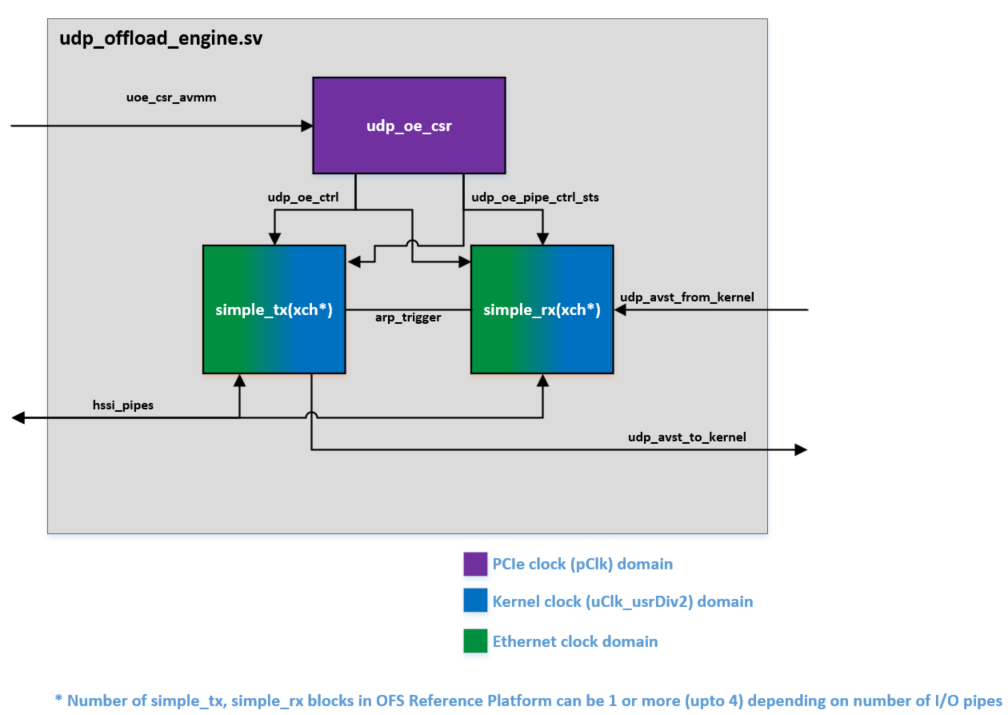
The UDP engine consists of a separate receive (rx) and trasmit (tx) path. The following functionalilty is performed by this reference design engine:
- Implements an Address Resolution Protocol (ARP) functionality to respond to be able to send & respond to ARP requests. This is needed for routing between different subnets using a gateway.
- Packetizes data from kernel to add the required header information (for MAC, IP & UDP layers)
- Extracts data from packets received by removing header information
- Handles clock crossing between kernel clock and Ethernet MAC clock domains
The source files for UDP engine used in oneapi-asp for OFS reference platform are located in oneapi-asp/Platform-Name/hardware/Board-Variant/build/rtl/udp_offload_engine directory.
Note: The same engine is used in the board variant with USM shown in Figure 5-5.
5.3.5 Hardware Compile Flow
Figure below shows the compile flow overview; the oneAPI compiler generated hardware circuit is compiled by Quartus® software along with design files for oneapi-asp.
Figure 5-9: oneAPI Compile Flow Overview

The oneAPI compiler uses the board_spec.xml to get more information about the oneapi-asp configuration. board_spec.xml file has a compile element to allow control of the Quartus® software compilation flow. The attributes of this element are discussed in section 2.1.2. The oneapi-asp uses tcl scripts to control the Quartus® software compilation flow. Figure 5-10 shows the flow and scripts used. All compilation scripts are located in oneapi-asp/Platform-Name/hardware/Board-Variant/build/scripts folder (location post oneapi-asp build flow).
Figure 5-10: Compilation Scripts in oneapi-asp

Table 5-11 summarizes notes for reference numbers 1-2 marked in figure above.
Table 5-11: Notes for Reference Numbers in Figure 5-10
| Reference Number | Note |
|---|---|
| 1 | revision_name is afu_flat for oneapi-asps for OFS reference platforms |
| 2 | gen-asp-quartus-report.tcl script generates a report (acl_quartus_report.txt) containing resource utilization and kernel clock frequency summary |
5.4 oneapi-asp Memory Mapped Device(MMD) Layer Implementation
As discussed in section 4.1, the MMD provides a set of API that allow the runtime to control the device and communicate with it.
The source code for MMD layer is located in oneapi-asp/common/source/host folder. aocl_mmd.h is the header file for the implemented API and is located in oneapi-asp/common/source/include folder. Table below summarizes the APIs that have been implemented in oneapi-asp for OFS reference platforms.
Note: For more details about the API, its arguments and enums please refer to the
aocl_mmd.hfile and to section 4.1.
Table 5-12: MMD API Implemented in oneapi-asp for OFS Reference Platforms
| API |
|---|
| aocl_mmd_get_offline_info |
| aocl_mmd_get_info |
| aocl_mmd_open |
| aocl_mmd_close |
| aocl_mmd_set_interrupt_handler |
| aocl_mmd_set_status_handler |
| aocl_mmd_yield |
| aocl_mmd_read |
| aocl_mmd_write |
| aocl_mmd_copy |
| aocl_mmd_program |
| aocl_mmd_host_alloc |
| aocl_mmd_free |
| aocl_mmd_shared_alloc |
| aocl_mmd_shared_migrate |
The implementation of these APIs is in oneapi-asp/common/source/host/mmd.cpp. The functions used in the implementation are distributed across various source files. Table below provides details on source code files.
Table 5-13: MMD Source Code Files
| Files/Folder | Description |
|---|---|
| mmd.cpp | This file has the implementation for all MMD API calls listed in table 5-12 |
| fpgaconf.h fpgaconf.c |
Contains bitstream reconfiguration function declaration(.h) & definition(.c) |
| kernel_interrupt.h | Contains KernelInterrupt class declaration; the class consists of functions to handle kernel interrupts |
| kernel_interrupt.cpp | Contains KernelInterrupt class constructor and function definitions |
| mmd_device.h | Contains Device class declaration, which stores device data and has functions to interact with the device |
| mmd_device.cpp | Contains Device class constructor and function definitions |
| mmd_dma.h mmd_dma.cpp |
Contain DMA functions declaration(.h) & definition(.cpp) |
| mmd_iopipes.h | Contains the iopipes class declaration(.h) |
| mmd_iopipes.cpp | Contains function definitions, these functions include iopipes class constructor as well as fucntions to detect and setup CSR space for IO pipes feature in board variants that support IO pipes |
| zlib_inflate.h zlib_inflate.c |
Function declaration(.h) and definition(.c) for decompressing bitstream data |
| CMakeLists.txt | CMakeLists.txt file for building MMD source code |
The build flow scripts build the MMD library, i.e. libintel_opae_mmd, and place them in oneapi-asp/Platform-Name/linux64/lib folder. The MMD library is specified as part of mmdlib, linklibs element in board_env.xml and used at runtime (refer to section 5-1 for sample board_env.xml file and section 2.2 for more information about board_env.xml elements).
Use of OPAE library in MMD
The MMD layer uses API from OPAE SDK for various device operations. Hence, the MMD layers requires OPAE library to be loaded to execute successfully. The mmdlib element specifies the libopae-c library to be loaded before the MMD library (demonstrated in sample board_env.xml in section 5-1).
Note: Please refer to Software Reference Manual: Open FPGA Stack for more information about OPAE SDK API. The document also has information about linux-dfl driver.
Use of Memory Properties Factory(MPF) library in MMD
In addition to OPAE, the MMD also uses API from Memory Properties Factory(MPF) software for memory operations. The libMPF library is compiled as part of oneapi-asp build flow and placed in oneapi-asp/Platform-Name/linux64/lib. This library is also loaded before the MMD library by specifying before libintel_opae_mmd in mmdlib element in board_env.xml.
Note: Memory Properties Factory(MPF) is a part of Intel® FPGA BBB. Please refer to Intel® FPGA BBB wiki for more information about MPF.
5.5 oneapi-asp Utilities Implementation
This section covers the implementation of board utilities (refer to section 4.2 for more information on board utilities) in oneapi-asp for OFS reference platforms.
Table below shows the source code/script locations for the utilities.
Table 5-14: oneapi-asp Utilities Source Code Locations
| Utility | Source Location |
|---|---|
| diagnose | oneapi-asp/common/source/util/diagnostic |
| program | oneapi-asp/common/source/util/reprogram |
| install uninstall initialize > Note: These are executable scripts |
oneapi-asp/common/linux64/libexec/ (copied to oneapi-asp/Platform-Name/linux64/libexec/ during oneapi-asp build flow, for more information about oneapi-asp build flow, refer to section 5.2) |
diagnose and program are compiled as part of the oneapi-asp build flow and executables are placed in oneapi-asp/Platform-Name/linux64/libexec/. A CMakeLists.txt file is provided for building the utilities, located in oneapi-asp/common/source/util directory.
The path to all of the above utility executables is used in utilbinder element in board_env.xml (demonstrated in sample board_env.xml in section 5-1). The runtime uses this when the corresponding aocl utility is invoked.
Brief descriptions for the source code files are given in table below.
Table 5-15: Brief Descriptions of oneapi-asp Utility Routines for OFS Reference Platforms
| File | Description |
|---|---|
| setup_permissions.sh | Helper script to configure correct device port permissions, make changes to allow users to lock pages in memory and set the hugepages required for the software stack to function correctly. The helper script is used by install, initialize routines |
| install | install routine invokes the setup_permissions.sh script after the FPGA Client Driver (FCD) is setup by the runtime |
| uninstall | uninstall routine reverts the port permission, memory locking and hugepage setting changes performed by install routine and is invoked by runtime after the FCD is removed by runtime |
| initialize | initialize routine performs the following steps: * looks for the initialization binary for the board variant to be initialized * extracts the FPGA hardware configuration file from the oneAPI fat binary using clang-offload-extract command provided by oneAPI Base Toolkit (Base Kit) version 2024.0 and beyond * invokes the setup_permissions.sh script to set correct device permissions* performs partial reconfiguration of the FPGA device by invoking program routine with the initialization bitstream as an argument >Note: For more information about how initialize utility extracts FPGA hardware configuration file from oneAPI fat binary, refer to Intel® oneAPI DPC++/C++ Compiler Handbook for Intel® FPGAs |
| program | program routine allocates memory and loads the supplied initialization bitstream in memory followed by a call to reprogramming function provided by oneapi-asp's MMD library. The MMD library uses fpgaReconfigureSlot API provided by OPAE library to perform device reconfiguration> Note: Please refer to Software Reference Manual: Open FPGA Stack for more information about OPAE SDK API |
| diagnose | diagnose routine scans for the available devices for the installed platform and performs DMA transactions between host & device. It also reports the DMA transfer bandwidth. diagnose routine uses functions provided by the MMD library for scanning & opening connection to available devices |
Appendix
Appendix A: Memory Mapped Device(MMD) Layer Debug Variables
The Memory Mapped Device(MMD) layer provides debug capability for custom ASP and oneAPI application developers. Snippet below shows how to set the variable and table below documents the environment variables that can be used to get debug information from the MMD layer at runtime.
export MMD_<DMA/ENABLE/PROGRAM>_DEBUG = 1
.<oneapi-binary> # Execute sample with MMD debug environment variable set
Table A-1: Environment Variable to Enable Debug Information in MMD
| Environment Variable | Set to Value | Description |
|---|---|---|
| MMD_DMA_DEBUG | 1 | Set this environment variable to see debug information for Direct Memory Access (DMA) transactions |
| MMD_PROGRAM_DEBUG | 1 | Set this environment variable to see debug information when the MMD reprograms the PR region |
| MMD_ENABLE_DEBUG | 1 | Set this to see debug information for all steps in the MMD layer. Maximum debug information is printed when this environment variable is set<> |
In addition to the debug variables provided by the MMD layer, there are debug variables provided by the Intel® FPGA Runtime for OpenCL™ Software Technology used in oneAPI base toolkit. For a full list of runtime debug variables, please refer to the Intel® FPGA Runtime for OpenCL™ Software Technology README.
Document Revision History
| Date | Release | Changes |
|---|---|---|
| May 26, 2023 | 2023.1 | First release of oneAPI Accelerator Support Package(ASP) Reference Manual: Open FPGA Stack on https://ofs.github.io/ |
| September 15, 2023 | 2023.2 | 1. Section 1: * Updated Figure 1-3 to add HSSI path 2. Section 2: * Added channels element in figure 2-1 and table 2-1, added information about board variants below this table* Added Section 2.1.8 on channels element3. Section 4: * Added information about MMD API (table 4-1) and new sections 4.1.1 to 4.1.21 4. Section 5: * Moved oneapi-asp build flow information into new section 5.2* Added new table 5-6 with oneAPI ASP board variants information * Added hardware design diagrams and information about new board variants with I/O pipes support (Hardware Design with IO Pipes and Hardware Design with IO Pipes and USM) * Updated hardware design diagrams to show PF/VF Mux/De-mux and added information about PF/VF mapping in section 5.3 * Added new section on UDP engine (section 5.3.4) * Updated figure 5-10 to remove import_opencl_kernel.tcl and add_bbb_to_pr_project.tcl* Updated table 5-13 to add mmd_iopipes.h and mmd_iopipes.cpp files |
| Dec 13, 2023 | 2023.3-1 | 1. Section 2: * Update table 2-5 to add information about port parameter * Added new section 2.1.4.1 on port parameter * Update table & figure numbers * Changed "master" and "slave" ports to "host" & "agent" ports in figures 2. Section 4: * Added new executable call supported by initialize utility 3. Section 5: * Updated initialize utility information to add clang-offload-extractcommand usage* Updated table with hardware design files information, added information about ofs_asp.sdc * Updated compile flow diagram, added information about new gen-asp-quartus-report.tcl script* Updated hardware implementation diagrams for signal name and IP name changes, replaced mem_if_vtp block with host_mem_if_vtp* Updated OpenCL Memory Bank Divider to Memory Bank Divider* Updated OpenCL Kernel Interface to Kernel Interface |
| Feb 2, 2024 | 2023.3-2 | 1. Section 5: * Updated Table 5-8 to add PF/VF mapping for different FIM configurations |
| Mar 19, 2024 | 2024.1 | 1. Section 1: * Added links for FIM developer guides for Agilex® 7 FPGA F-Series Development Kit (2x F-Tile) and Agilex® 7 FPGA I-Series Development Kit (2x R-Tile and 1xF-Tile) * Added link to Intel® oneAPI DPC++/C++ Compiler Handbook for Intel® FPGAs * Updated figure 1-3 to rename OpenCL Memory Bank Divider to Memory Bank Divider2. Section 2: * Replaced links to FPGA Optimization Guide for Intel® oneAPI Toolkits with links to Intel® oneAPI DPC++/C++ Compiler Handbook for Intel® FPGAs * Fixed format for table 2-6 * Updated figure 2-6 to rename OpenCL Memory Bank Divider to Memory Bank Divider* Replaced broken link for USM (Unified Shared Memory) 3. Section 3: * Updated Memory Bank Dividersection to add information about memory_bank_divider_hw.tcl. Replaced figure showing GUI for the IP with parameters in memory_bank_divider_hw.tcl and added information about these parameters in table 3-1 * Updated port name acl_bsp_snoop to acl_asp_snoopand acl_bsp_memorg_host to acl_asp_memorg_host in table 3-2* Updated Kernel Interface section to add information about kernel_interface_hw.tcl. Replaced figure showing GUI for the IP with parameters in kernel_interface_hw.tcl and added information about these parameters in table 3-34. Section 5: * Replaced board_env.xml figure with code snippet* Added links to README for fseries-dk & iseries-dk oneapi-asp folders in section 5.1* Updated directory structure in section 5.1 and added information about design files common to oneapi-asp for OFS reference platforms * Update file paths in table 5-2 * Update section for script file name changes from build-bsp.sh to build-asp.sh, setup-bsp.py to setup-asp.py, build-bsp-sw.sh to build-asp-sw.sh* Updated figure 5-2 to add a step in build-asp.sh script to copy common files to platform directory* Added Note on OPAE_SDK_REPO_BRANCH environment variable in table 5-5* Added new OFS reference platforms ( fseries-dk and iseries-dk) in table 5-6* Update section for design file name changes from board.qsys to board_hw.tcl, ddr_board.qsys to ddr_board_hw.tcl, ddr_channel.qsys to ddr_channel_hw.tcl, bsp_logic.sv to asp_logic.sv, bsp_design_files.tcl to asp_design_files.tcl* Updated signal names bsp_mem_if to asp_mem_if, acl_bsp_memorg_host to acl_asp_memorg_host, host_mem_if_pa_bsp to host_mem_if_pa_asp* Updated hardware implementation diagrams (figure 5-2 to 5-5) for new file, signal names * Added information about RTL files to table 5-7 * Added iseries-dk_1pf_1vf.ofss in table 5-8* Fixed section 5.3.1 header and added more information about PIM blocks in section 5.3.1 * Added new section 5.3.3 on board_hw.tcl* Updated figure 5-10 to add information about ip-deploy and qsys-generate for board_hw.tcl5. Appendix: * Added appendix section with MMD debug variable information |
Notices & Disclaimers
Intel® technologies may require enabled hardware, software or service activation. No product or component can be absolutely secure. Performance varies by use, configuration and other factors. Your costs and results may vary. You may not use or facilitate the use of this document in connection with any infringement or other legal analysis concerning Intel products described herein. You agree to grant Intel a non-exclusive, royalty-free license to any patent claim thereafter drafted which includes subject matter disclosed herein. No license (express or implied, by estoppel or otherwise) to any intellectual property rights is granted by this document, with the sole exception that you may publish an unmodified copy. You may create software implementations based on this document and in compliance with the foregoing that are intended to execute on the Intel product(s) referenced in this document. No rights are granted to create modifications or derivatives of this document. The products described may contain design defects or errors known as errata which may cause the product to deviate from published specifications. Current characterized errata are available on request. Intel disclaims all express and implied warranties, including without limitation, the implied warranties of merchantability, fitness for a particular purpose, and non-infringement, as well as any warranty arising from course of performance, course of dealing, or usage in trade. You are responsible for safety of the overall system, including compliance with applicable safety-related requirements or standards. © Intel Corporation. Intel, the Intel logo, and other Intel marks are trademarks of Intel Corporation or its subsidiaries. Other names and brands may be claimed as the property of others.
OpenCL and the OpenCL logo are trademarks of Apple Inc. used by permission of the Khronos Group™.